|
Home
Why an RV?
Choices
Search
Empennage
Empennage Attach
QB Wings
Bulkheads
Aft/Center Fuselage
Forward Fuselage
Cockpit 1
Cockpit 2
Cockpit 3
Tip up Canopy 1
Tip up Canopy 2
Tip up Canopy 3
Avionics/Panel 1
Avionics/Panel 2
Avionics/Panel 3
Avionics/Panel 4
Firewall
Tricycle Gear
Engine/Prop 1
Engine/Prop 2
Cowling 1
Cowling 2
Baffling
Ram Air
Last 10 Percent
Last 5 Percent
Last 3 Percent
Last 1 Percent
Phase 1
Phase 1 pg. 2
Phase 2
P-Mag Install
Videos
EFIS Flight Logs
Tips & Mods
Links
Fine Living
Avionics Manuals
N447RV Documents
Helpful Builder Docs
FAA Documents
Contact Information

The Boo
| |
Cowling 1
| 11/1/04 |
Don't forget to VOTE today! Vote for Bush! Sorry
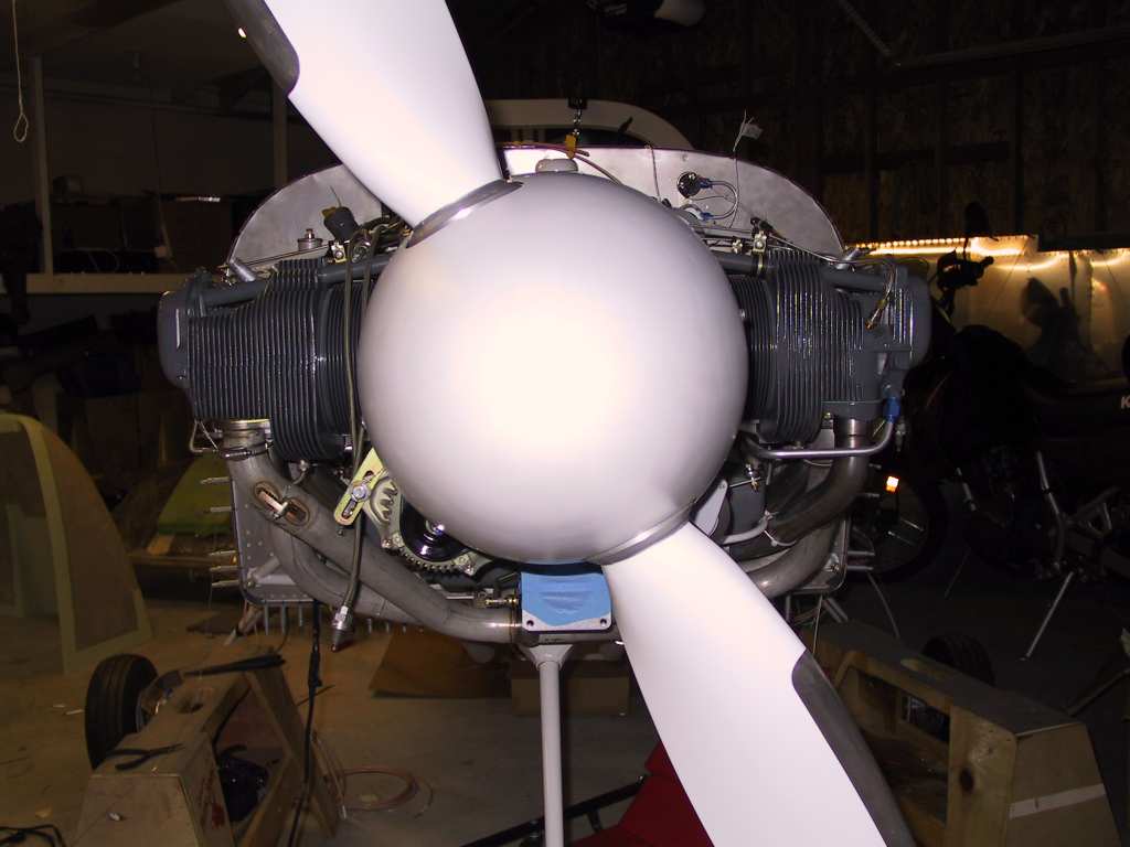
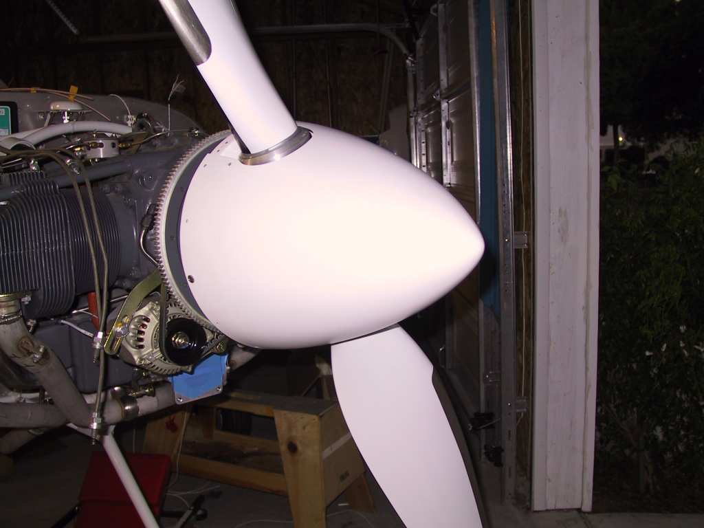
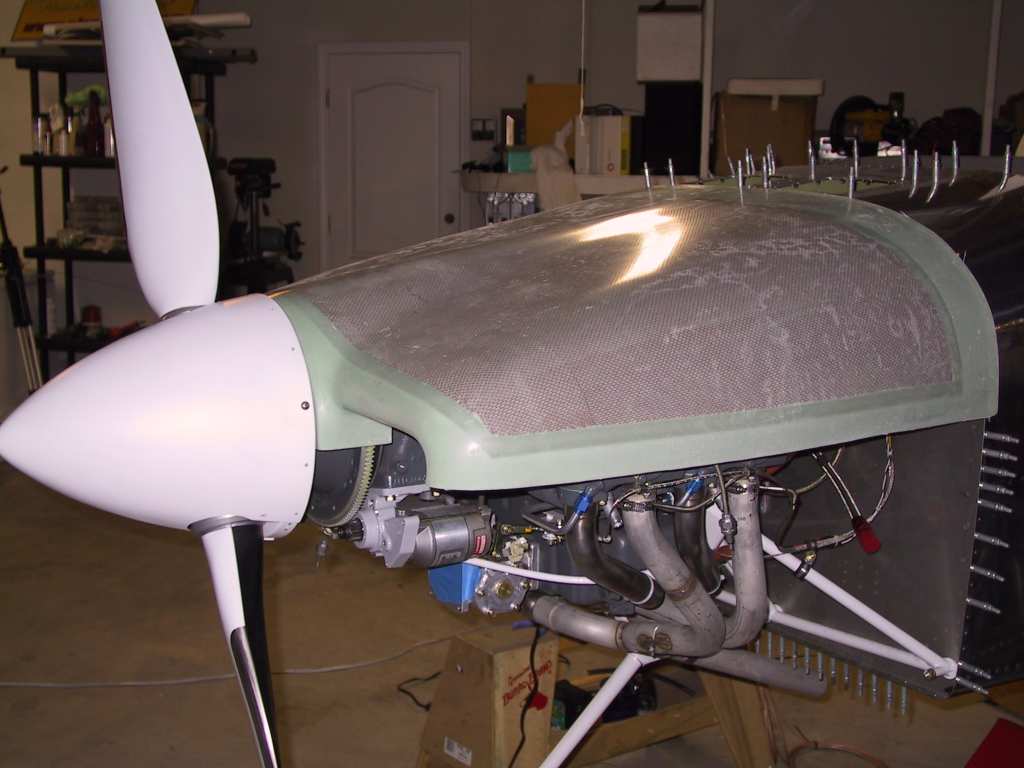
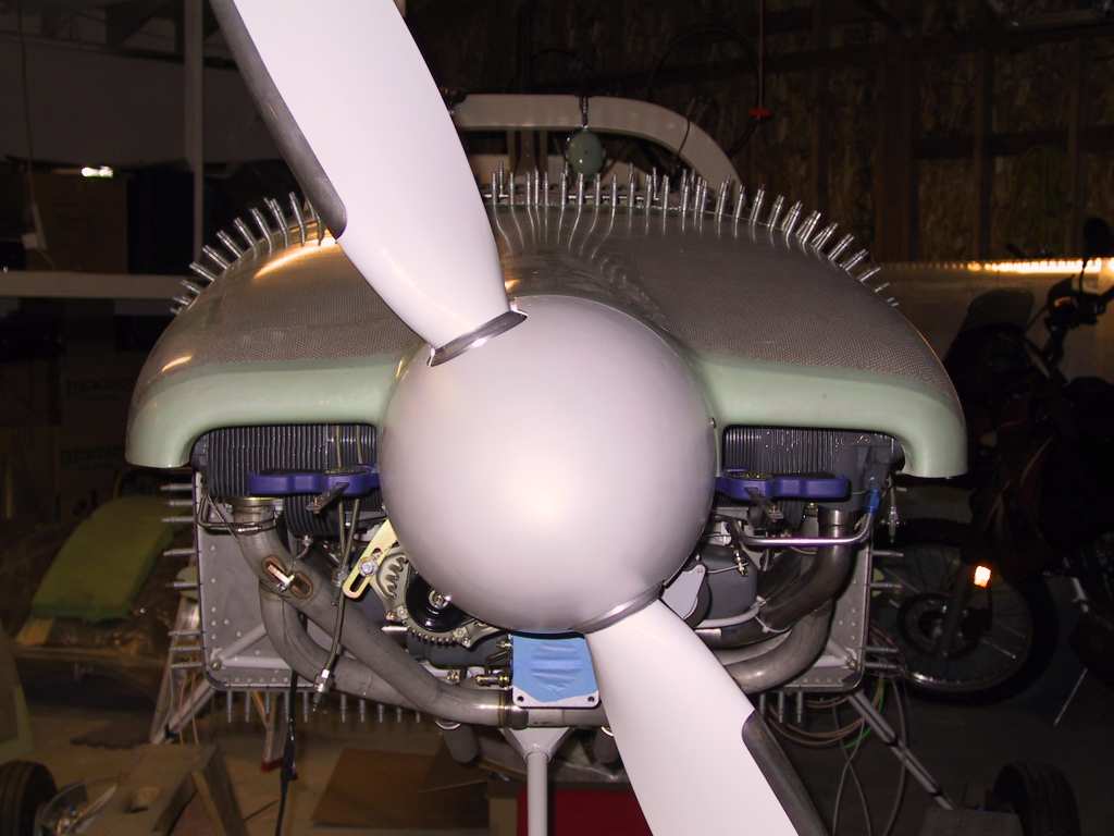
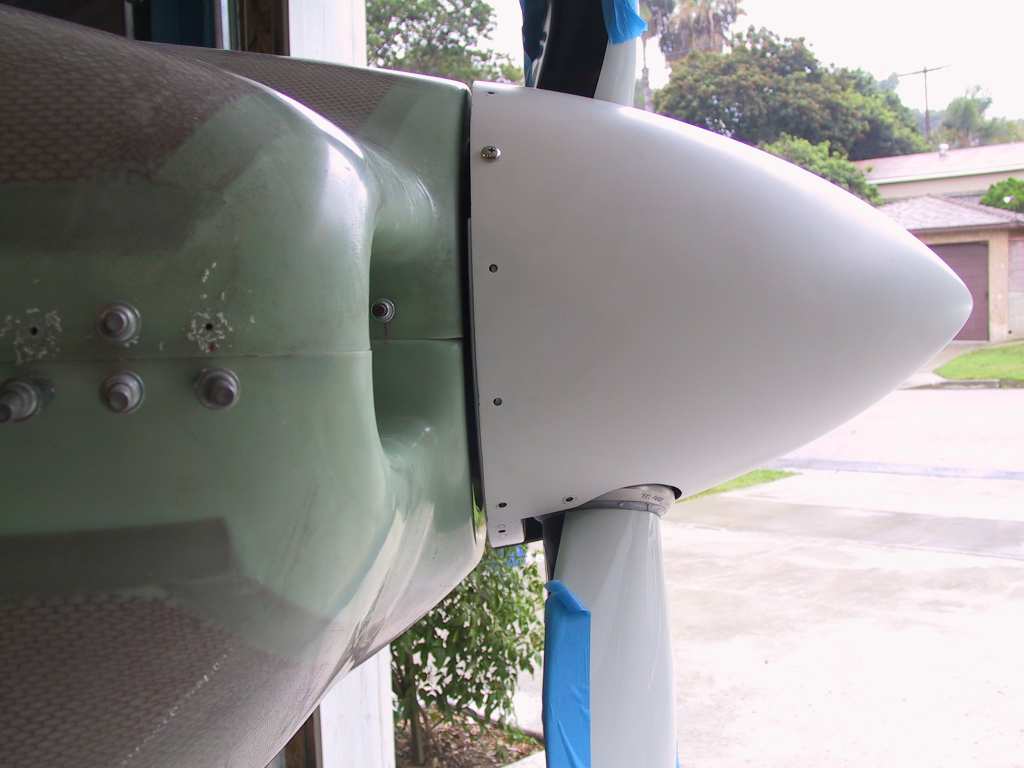
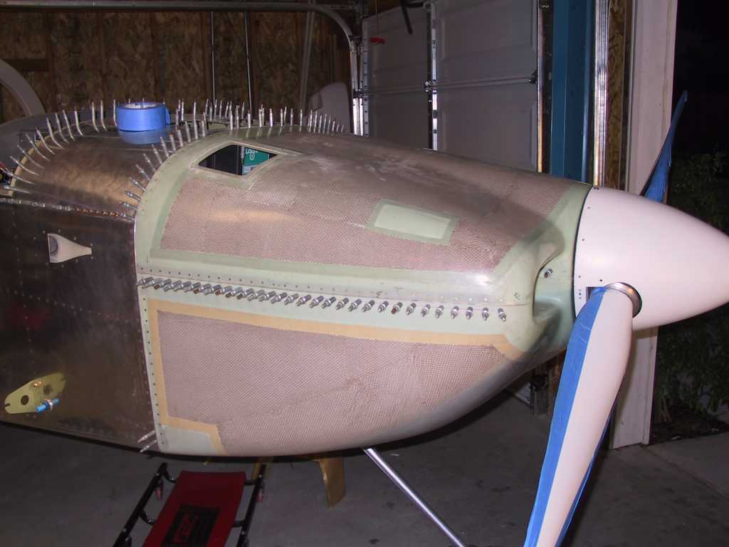
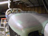
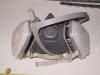
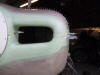
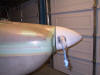
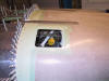
Mom :) Got the spinner on in preparation for fitting the cowling.
One thing that's *really* nice about the WhirlWind props that you don't
necessarily think about when selecting a prop is that it comes with a
prefabricated spinner. It's very well made, I am really surprised how
nice it fits. I don't know how long it takes to make Vans spinner but
those hours won't show up in my log.
  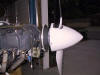
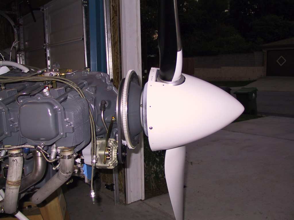
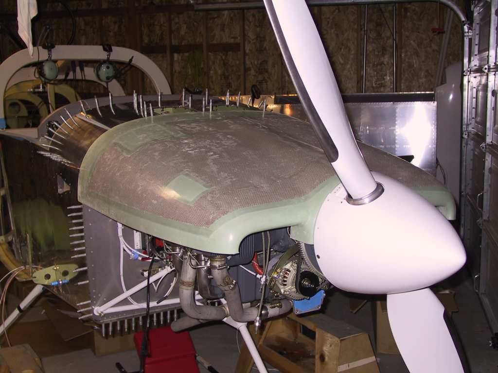
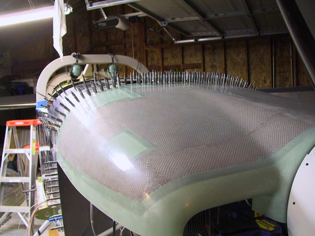
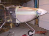
Then I stuck the top cowl on to test fit it. Fits pretty well.
I'll start on this fabrication as soon as I'm done with the last few wires
to run. I've been waiting on parts since last week. You think
that when you order parts "next day air" on a Thursday that they would
arrive at least by Monday? Jeeeese what is up with these people.
   |
| 11/2/04 |
Still waiting on parts. And I didn't get the shims cut
for the cowling. Studied plans, drank beer, watched Bush win.
Yeah! Four more years! |
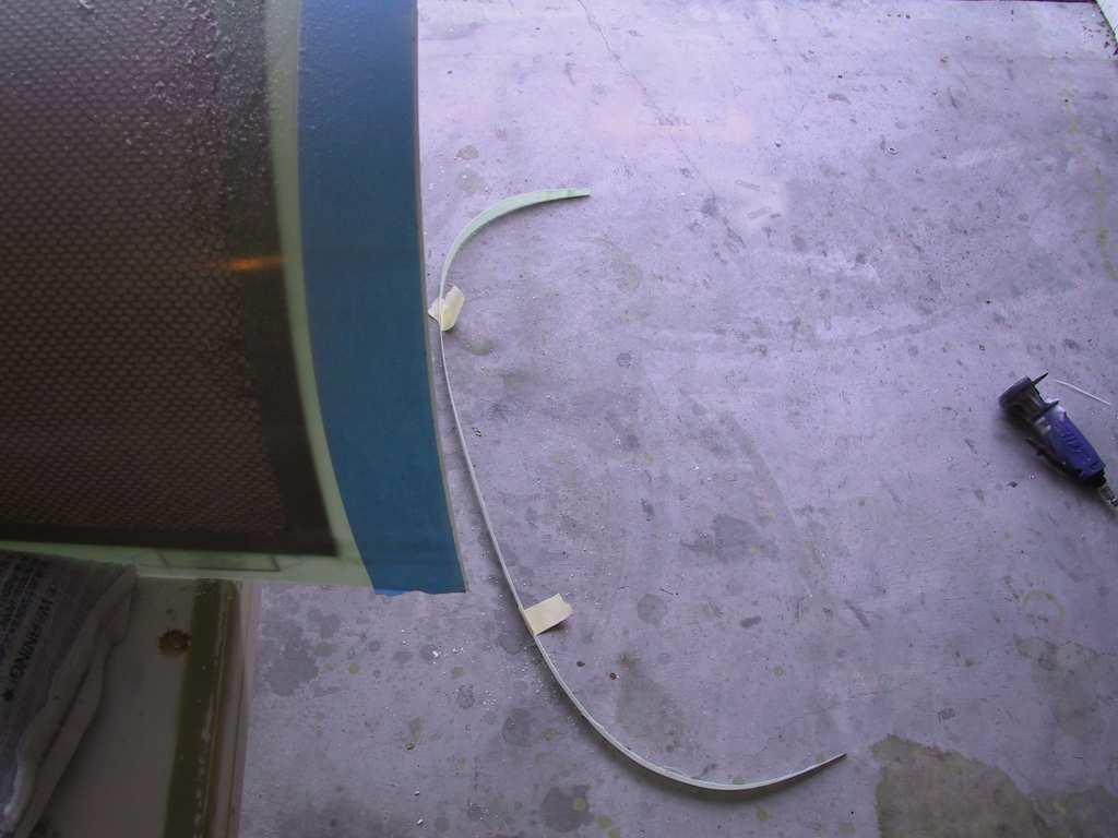
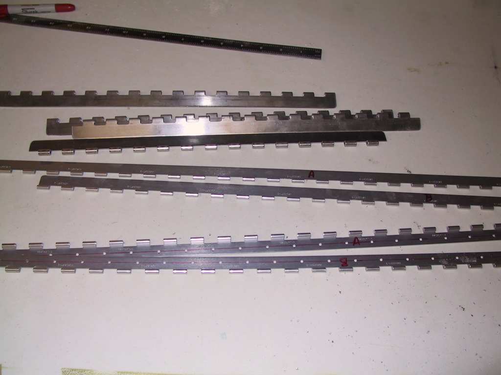
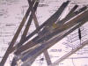
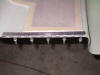
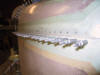
| 11/3/04 |
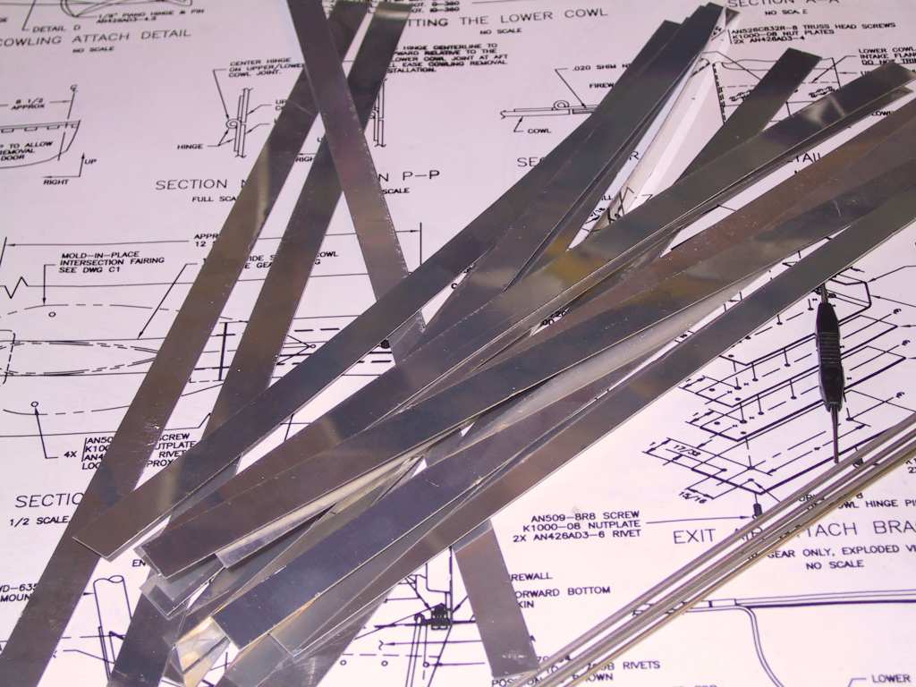
Left from work and headed over to the EAA Chapter 96 hangar
and used the shear to make these .020 shims. The biggest problem was
getting the blue plastic off of them afterwards. Gotta remember to do
it before cutting next time. Do you think I made enough of them?
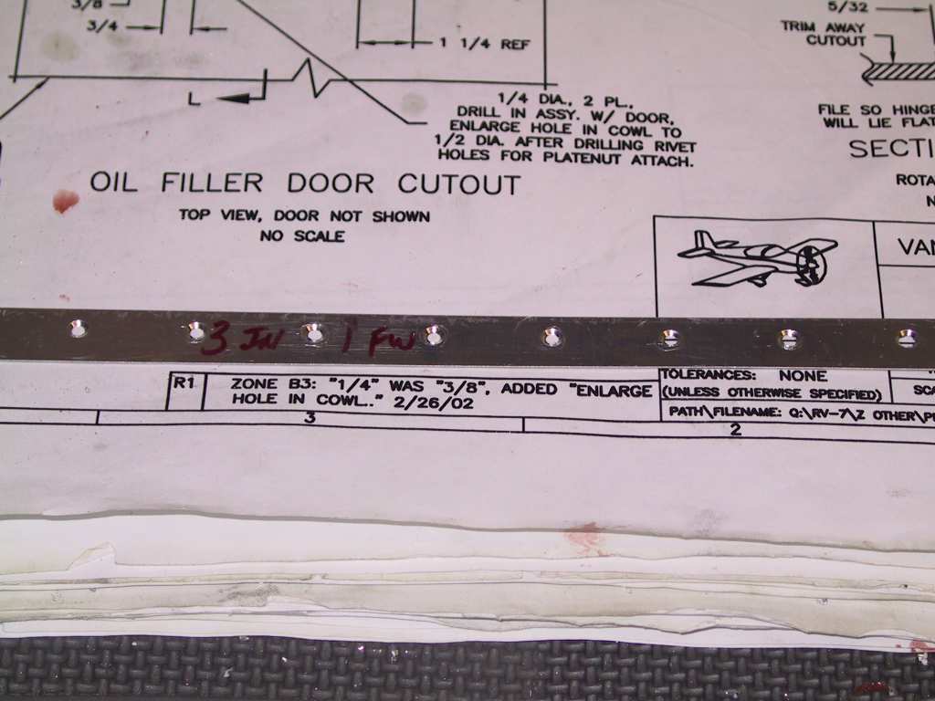
Clamped the shim and hinge to the right side first and began drilling.
Remember to leave the gap between the left and right hinges so you can get
to the hinge pins through the oil filler door.
Drilled the hinges using the existing holes.
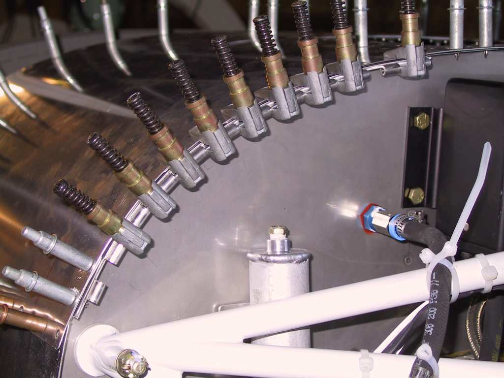
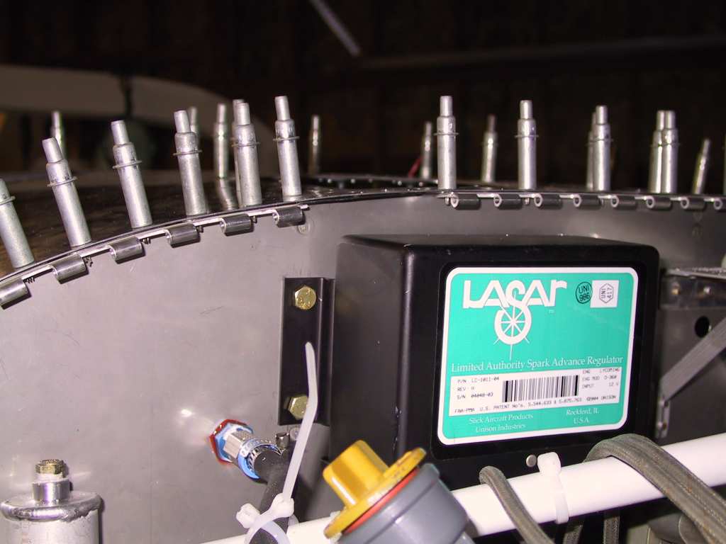
I'm going to have to figure out a clever way to fix the hinge pins in
place with the LASAR box in the way. Oh well, no biggie.
Countersunk the shim.
Re-clecoed the hinge with the cowling side back onto the firewall.
Tossed on the top cowl and marked forward 2 inches and taped. This
will be my cut line.
I held the cowl in place using two clamps on the starter ring gear.
The cowl just rests on top of them, one on each side. Nuf for tonight.
  |
| 11/4/04 |
I whacked off the rear portion of the top cowl using the
same method and tools as used for the canopy. But, you don't have to
worry about this cracking, fortunately.
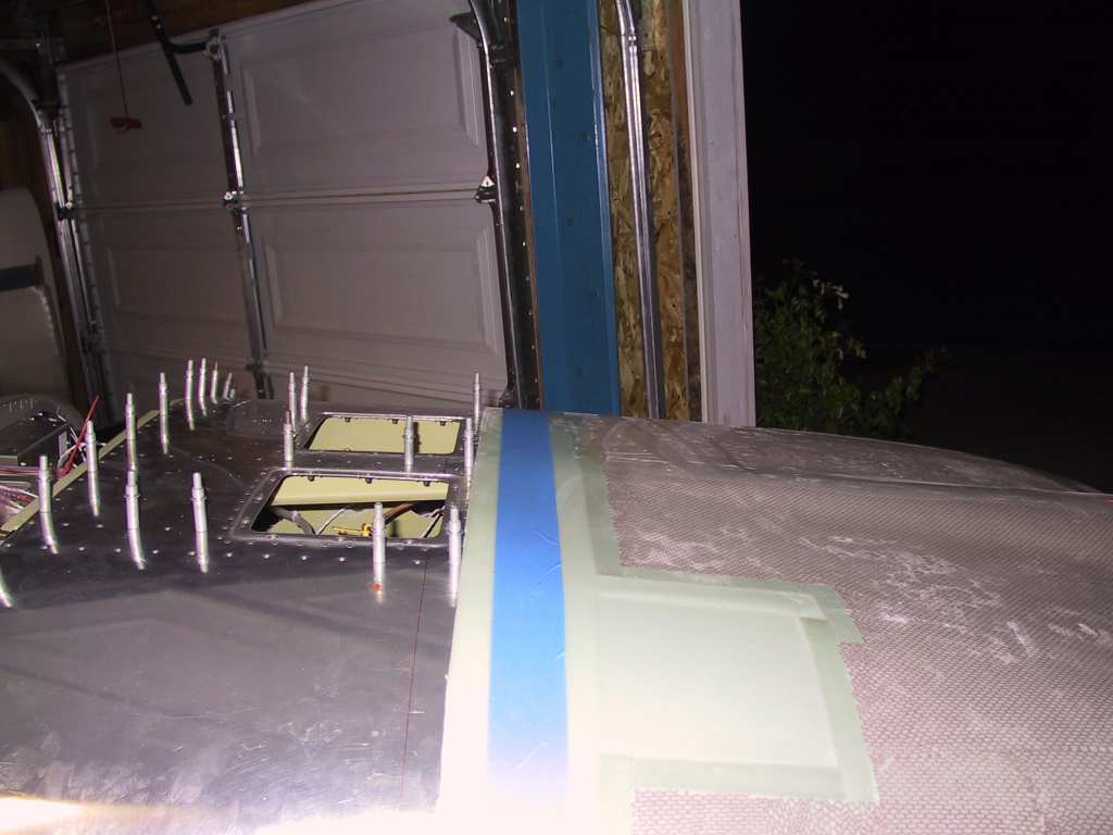
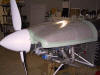
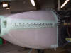
After test fitting I was a bit confused. With shims the canopy is
low against the fuselage top skin. So I tried it without the shims.
Perfect. I sure wish Vans would keep their plans up to date.
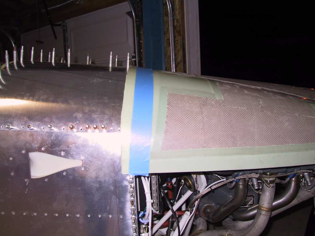
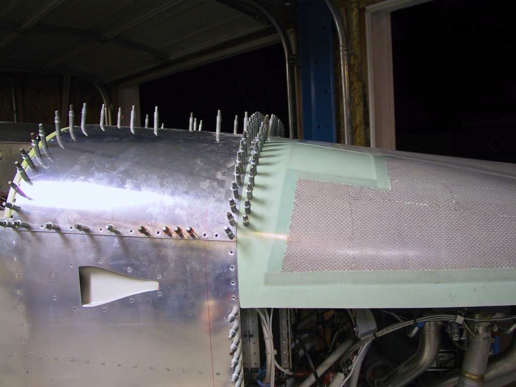
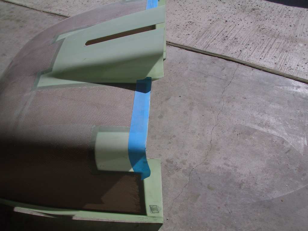
With these new thinner cowls you don't need any shims. In fact, you
could say that a .05 shim could be used on the cowling side! Here are
some shots without the shims.
Don't forget to leave a small gap for paint between the cowl and skins.
Here I'm just eyeballing it. I haven't figured out the perfect gap
yet. In fact I'm going to mount and drill the top and bottom halves
and then sand and file afterwards. Reason is that you can *Never* get
the thing back into the same position after you take it off 1 bazillion
times to sand here and there. Once you drill it and have clecoed it on
it doesn't budge.

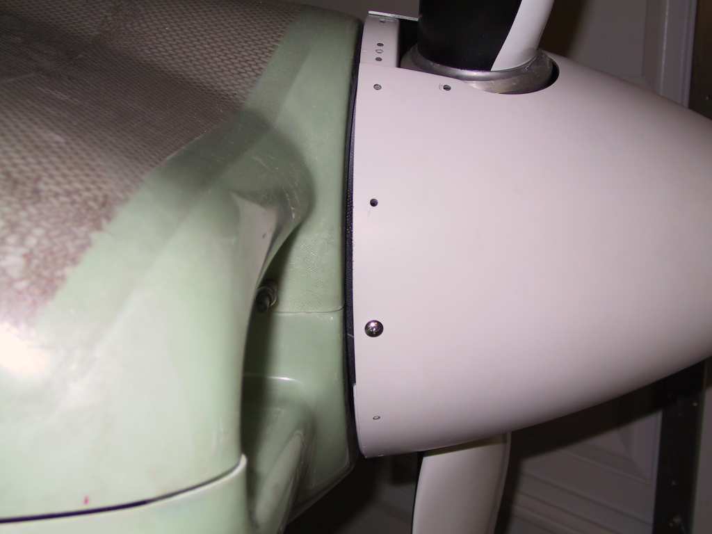
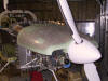
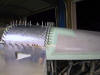
Made sure that the spinner sat just about 3/16ths above the cowl.
The gap between the spinner and cowl is 3/16ths at the top and 1/4 at the
bottom. Good enough.
Drill that sucker. The plans say to drill just a few holes for
clecos. I'm not trusting the plans at all at this point.
Cut the bottom hinges to 11 inches and I'll drill them tomorrow.
Bulbous One Boob Betty.
 |
| 11/05/04 |
Feeling like crap. Time for a day off. |
| 11/06/04 |
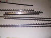
Well today began with the usual trip to Aircraft Spruce for
some needed parts. Here's one of the two hinges I'll use for the oil door
latch.
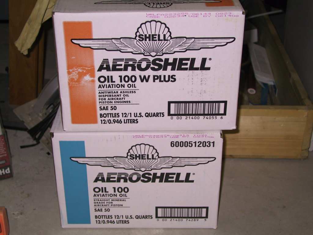
Mineral and 100W oil for the future first engine start. I couldn't
resist.

Epoxy for the canopy work. I got the 206 hardener. It's the
slow stuff. I may need to buy the 205 faster stuff if this is too
slow.
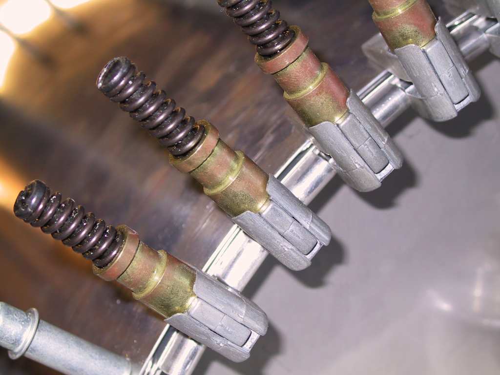
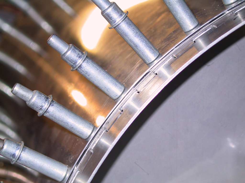
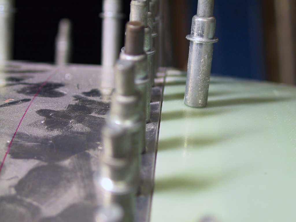
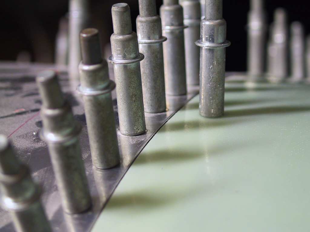
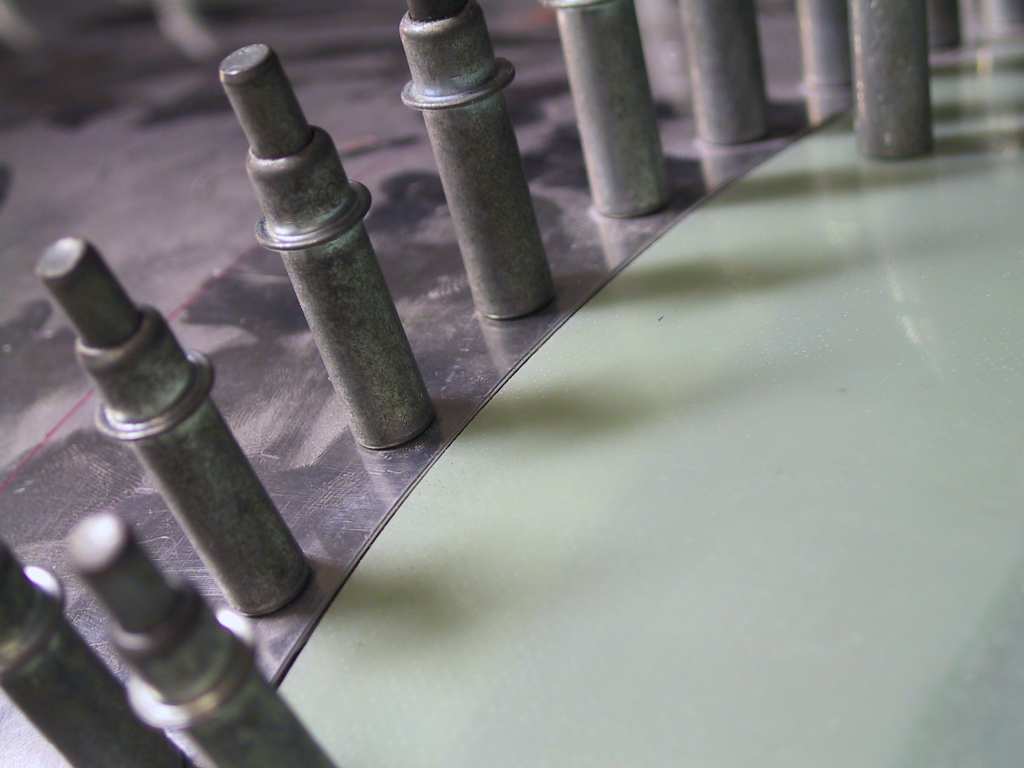
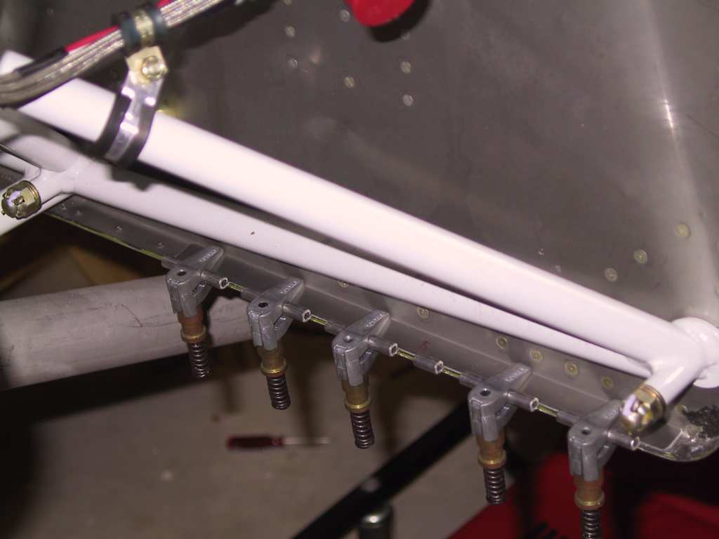
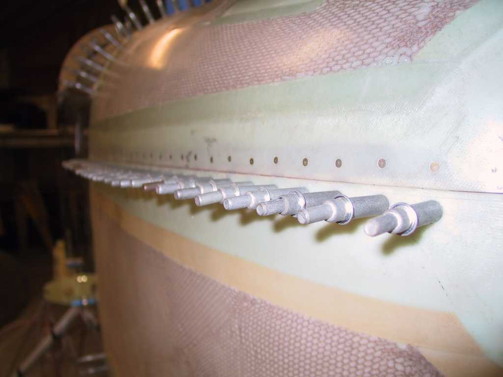
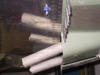
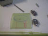
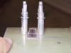
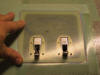
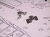
Got some other assorted goodies in the mail too. Here are the
*machined* High Density pins I've been waiting for. Every other store
I contacted was so incompetent. It seems that no one has even heard of
machined pins. Have you ever tried to crimp HD connectors with the
tabs? What a waste of time. These crimp with your standard
barren crimper which is nice since you don't have to buy a special tool.
I like Allied!
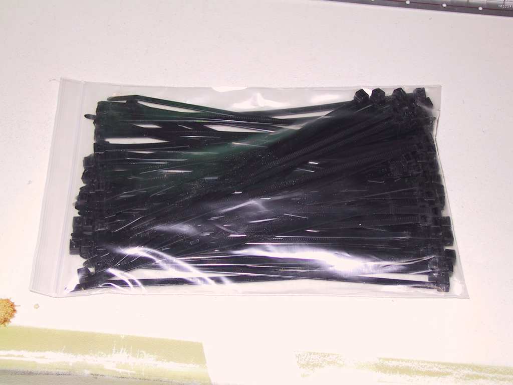
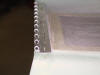
And here's the backorder from Steinair. One hundred heat resistant
tie wraps which I'll use in the engine compartment exclusively.
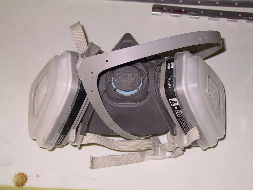
Okay, were getting into the fiberglass now. Put this on.
Nothing really to say when sanding and cutting the cowl. Just go
slow. I may have made a mistake cutting the lower cowl where it meets
the top cowl towards the back. The gap is larger than I want, about
1/8" inch. Looks like shit IMHO. I'm going to go with it and see
what happens. Damn I hate to make mistakes. And the problem is I
don't know where I made it yet.
    |
|
11/8/04 |
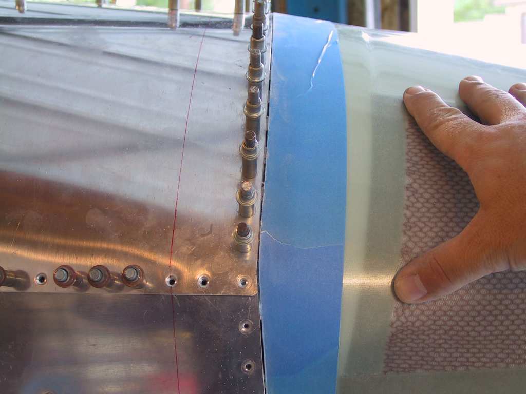
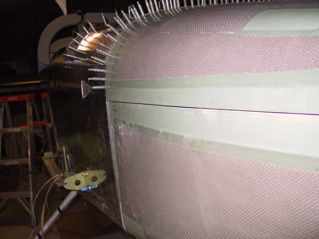
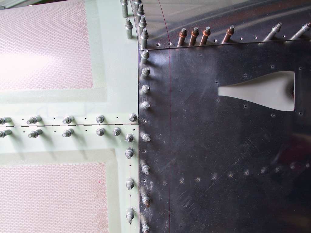
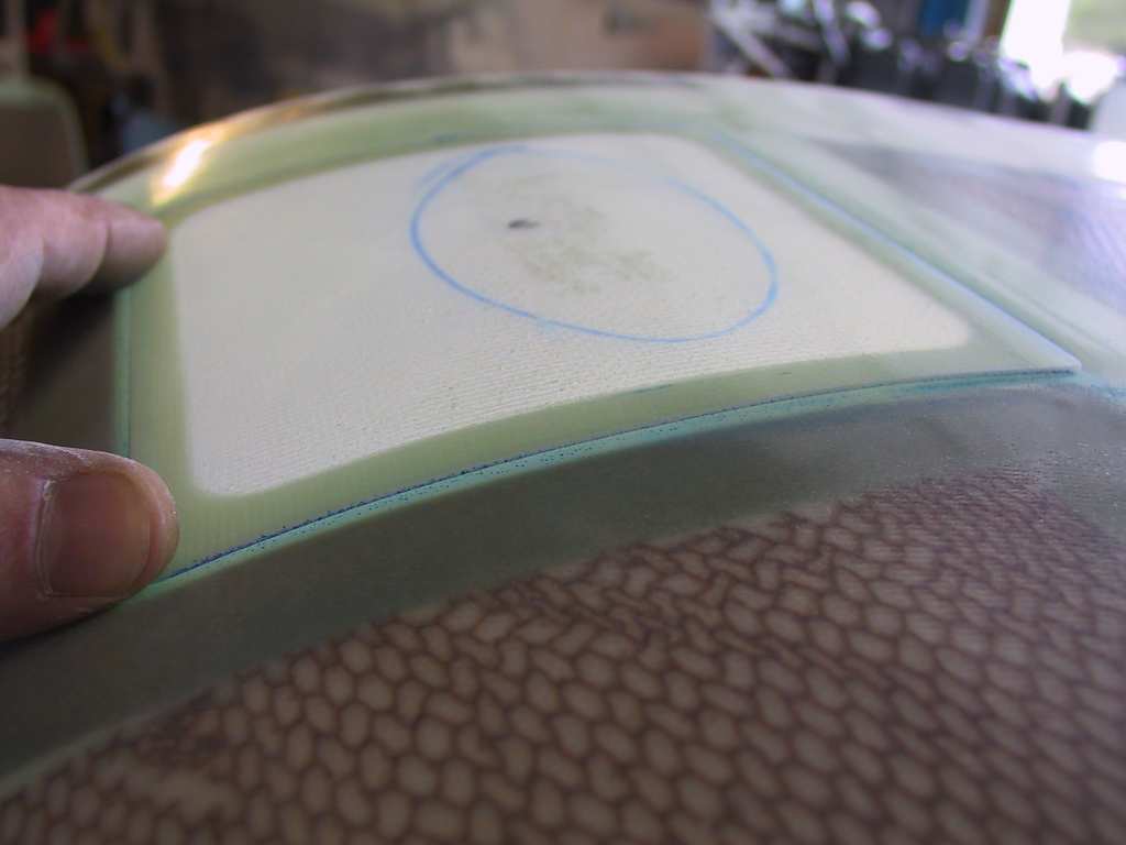
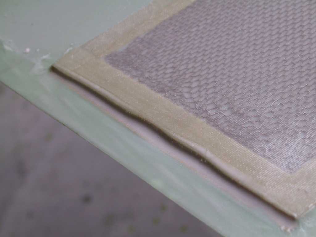
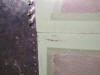
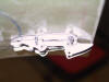
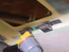
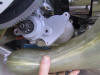
Well I think I figured out what is happening between the
upper cowl (which fits perfect) and the lower piece of dung cowl.
Turns out that the lower cowl is definitely not what you would expect from
vans. The honeycomb weave which is embedded into the cowl is too far
aft and the hinges are bent at awkward angles. So I called Vans and of
course their questions were on the mark and we determined that I should just
sand the areas where the honeycomb and hinges meet. Great. Lucky
me. Here's what I'm talking about. And the other side is worse.
Anyway it's still looking ok I guess but I'm concerned about the gap.
It doesn't look too bad in these pictures but that's because I can't take
good pictures.
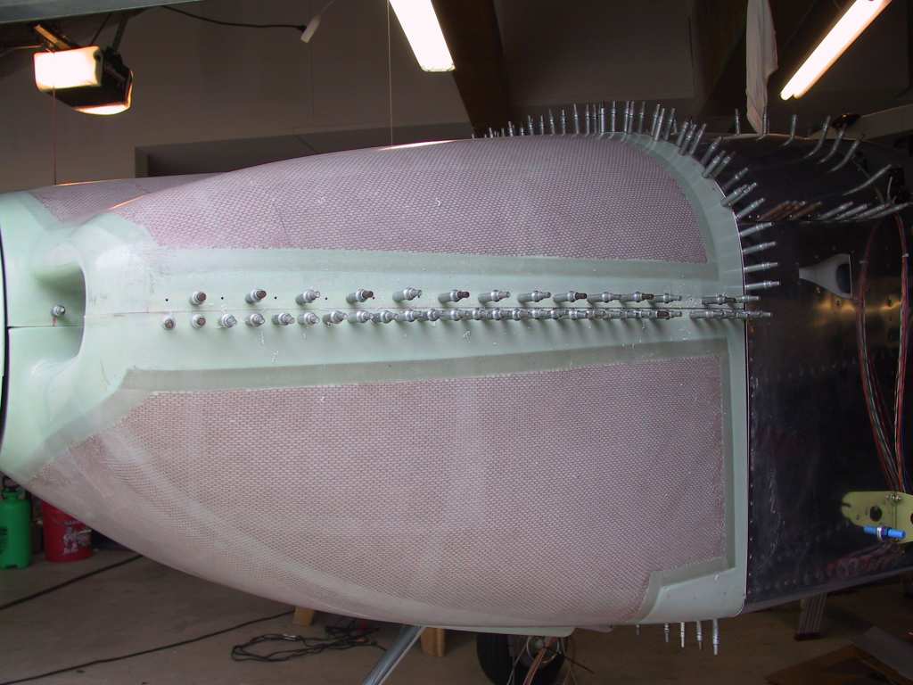
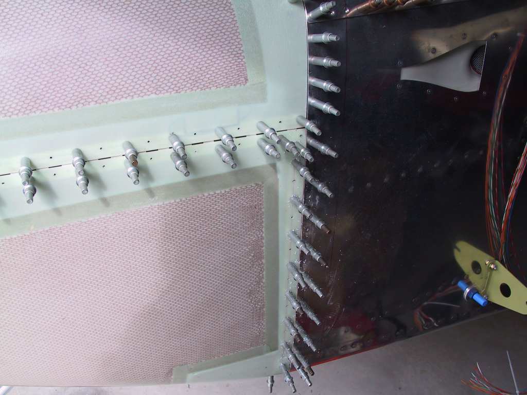
Gonna have fun trying to rivet these!
So I ground down the material and really slathered on the epoxy and micro
balloons. Looks messy but it isn't coming off, ever. I figure if
I ever have to replace (or someone else) the cowl, they better get on the
phone and order a new one (which I may be doing anyway).
 |
| 11/9/04 |
Halo 2 - no airplane work. |
| 11/10/04 |
Halo 2 - no airplane work. I needed a break anyhow. |
| 11/11/04 |
Yep I'm addicted. Halo 2. |
| 11/12/04 |
No Halo 2 and no airplane work. I need a break from
both. |
| 11/13/04 |
Back in business. Let's get this oil door done baby!
Trimmed the oil door and test fit it into the recess. The recess is
sort of vague on my top cowl. Will this cowl nightmare ever end?
Anyway, just drill it.
It actually fits pretty nice.
Okay, here's the buggaboo. Forget this lower cowl. I'm not going
to settle. I'll order a new lower cowl from Vans on Monday.
Oh well just bite the bullet and order a new one and if it comes with the
same defect then send it back until I get one that isn't a screwed up.
You have to remember one thing here, if you want a nice new Cessna 172 with
a Garmin 1000 stack it's going to cost you over 230K. So spending a
few extra hundies on my plane is still cost effective. At least the
top cowl is ok. Unfortunately, vans doesn't list the cost of the cowl
on their website. I guess it could be more than a few hundies :( |
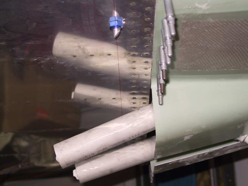
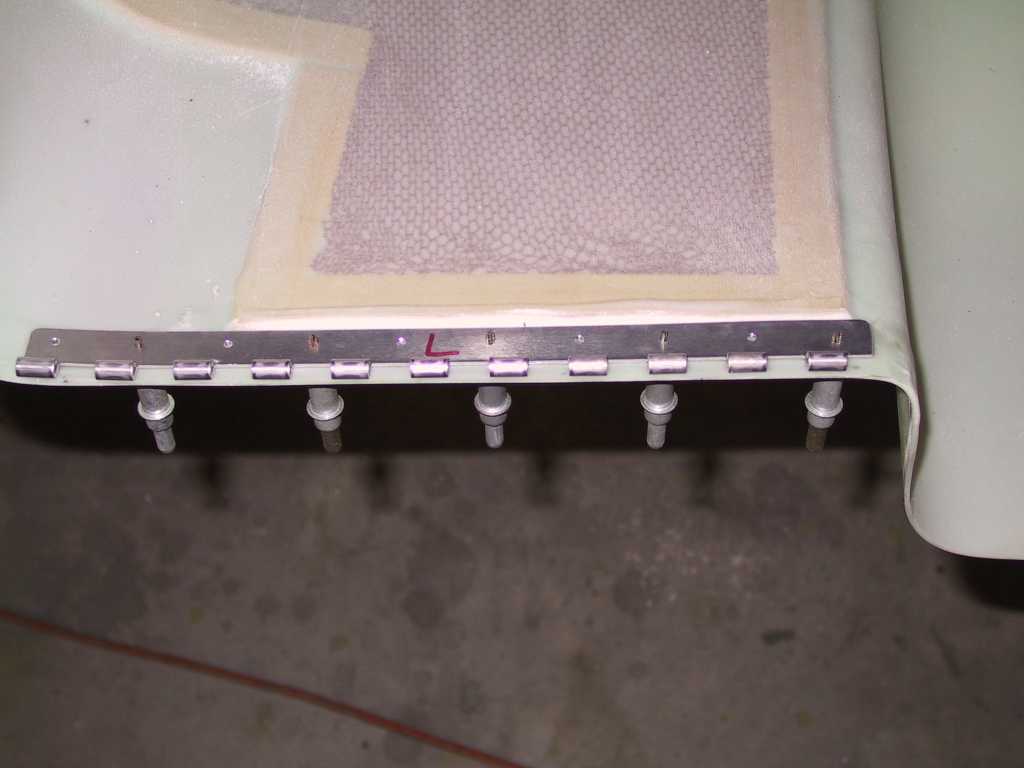
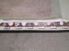
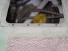
| 11/27/04 |
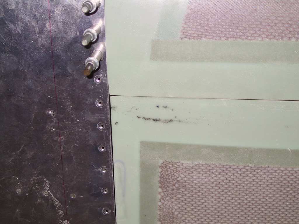
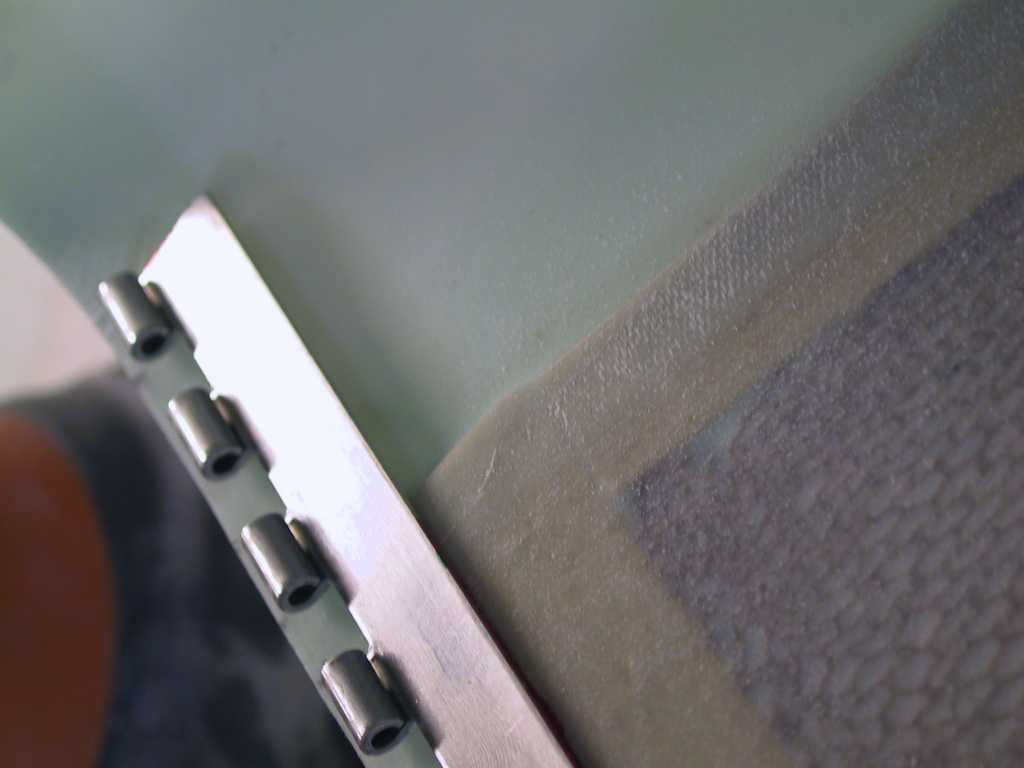
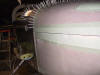
Got the new lower cowl from Vans. Spent the better
part of a week getting it "correctly" fit. It turns out that I have
the same issue with this cowl as I had with the last one, which is that I
have to trim some of the honeycomb, but not nearly as much. In fact I
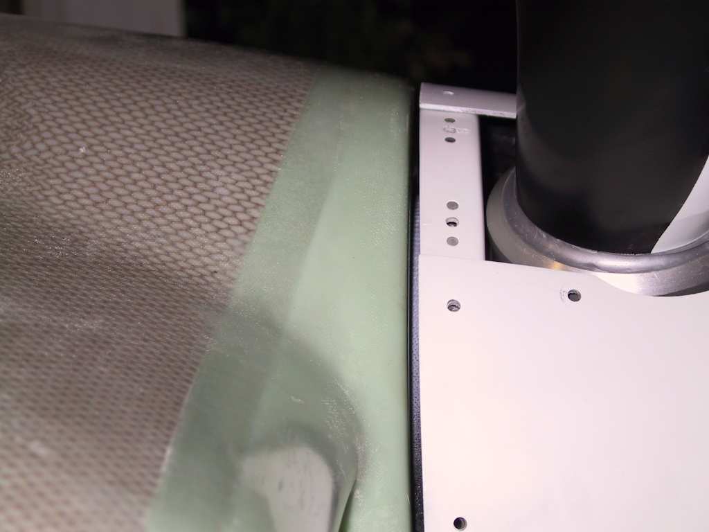
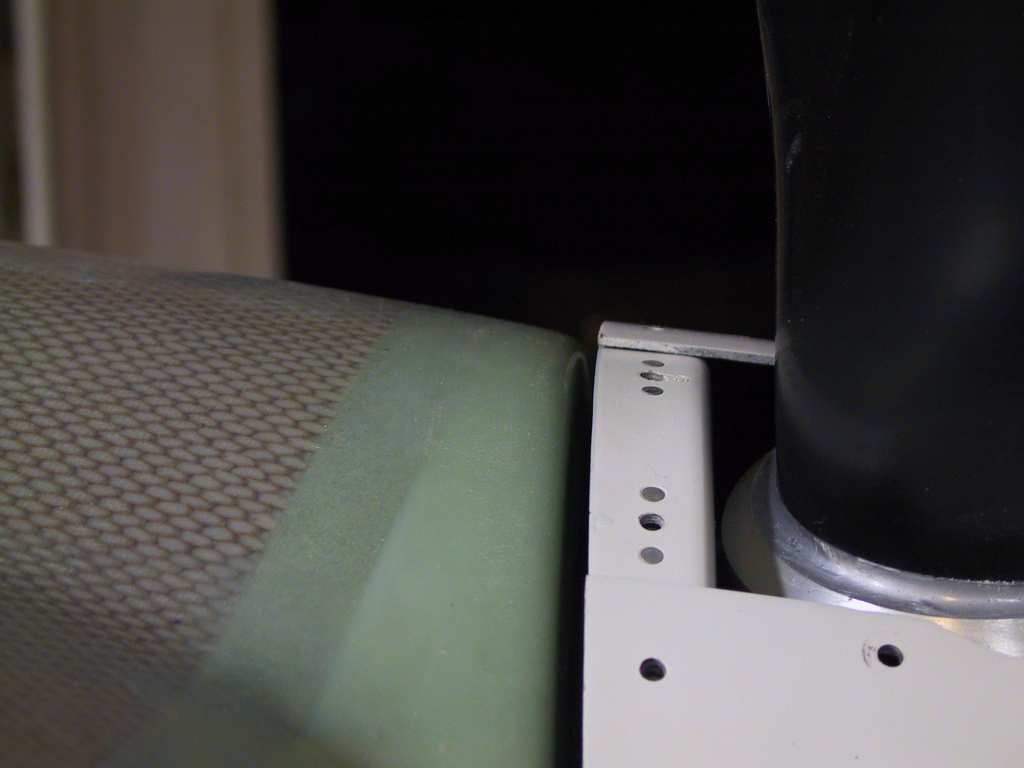
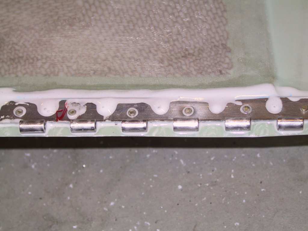
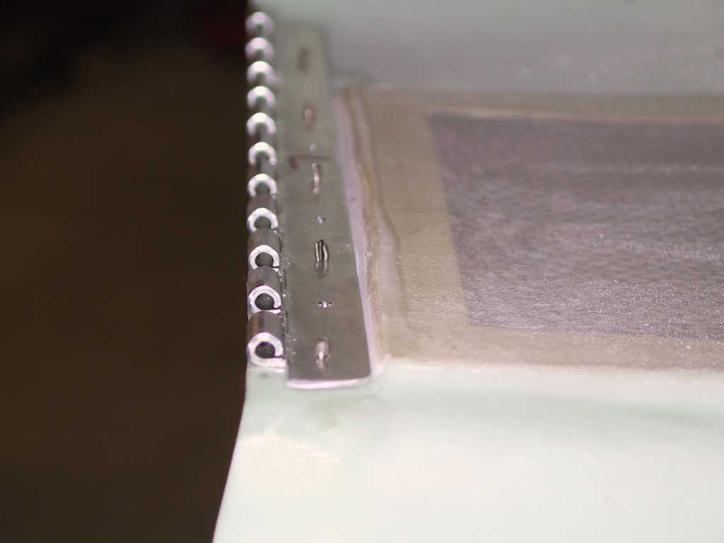
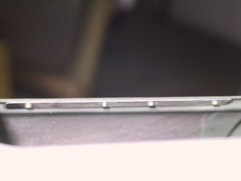
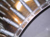
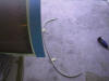
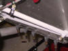
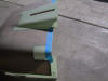
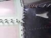
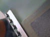
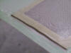
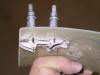
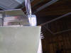
had to trim it just barely. Here you can see that the hinge will not
lay flat.
 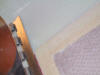
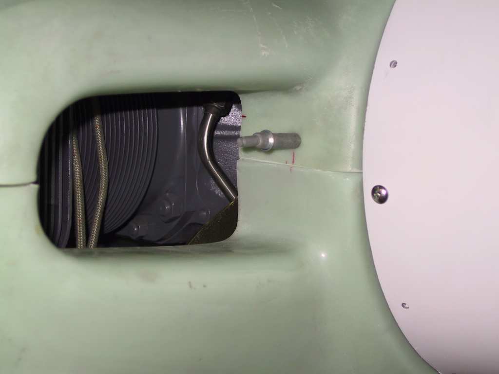
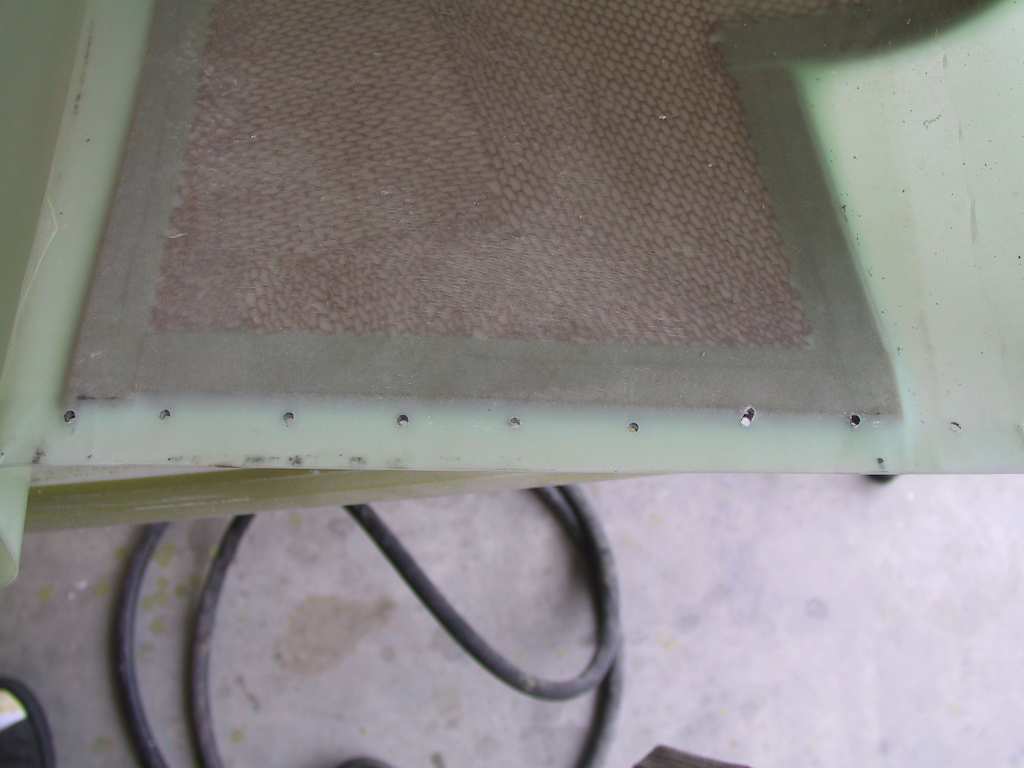
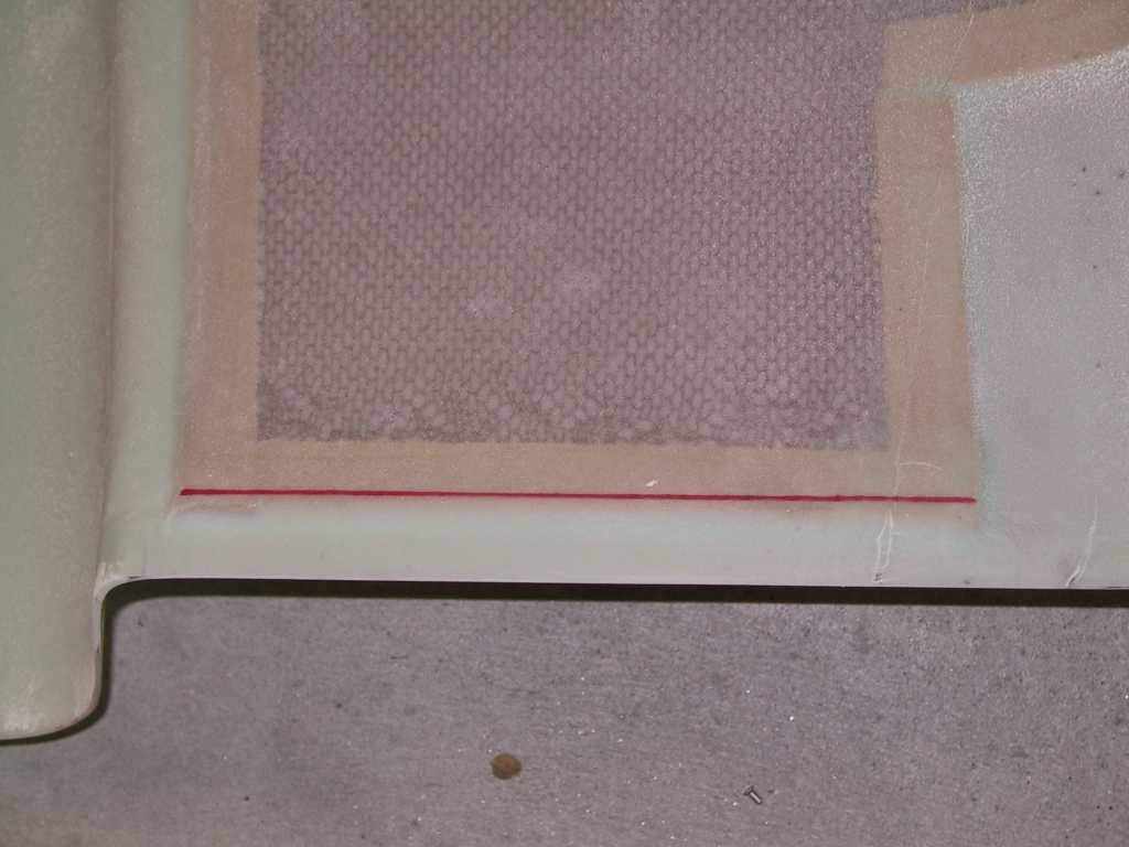
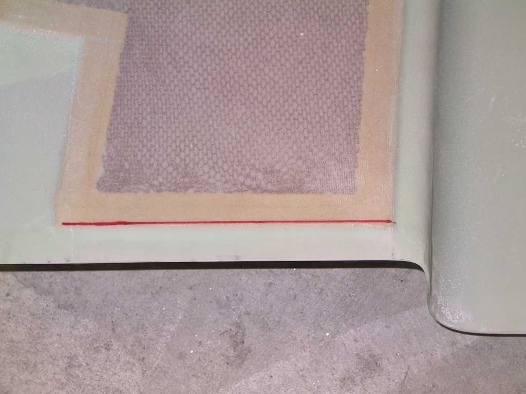
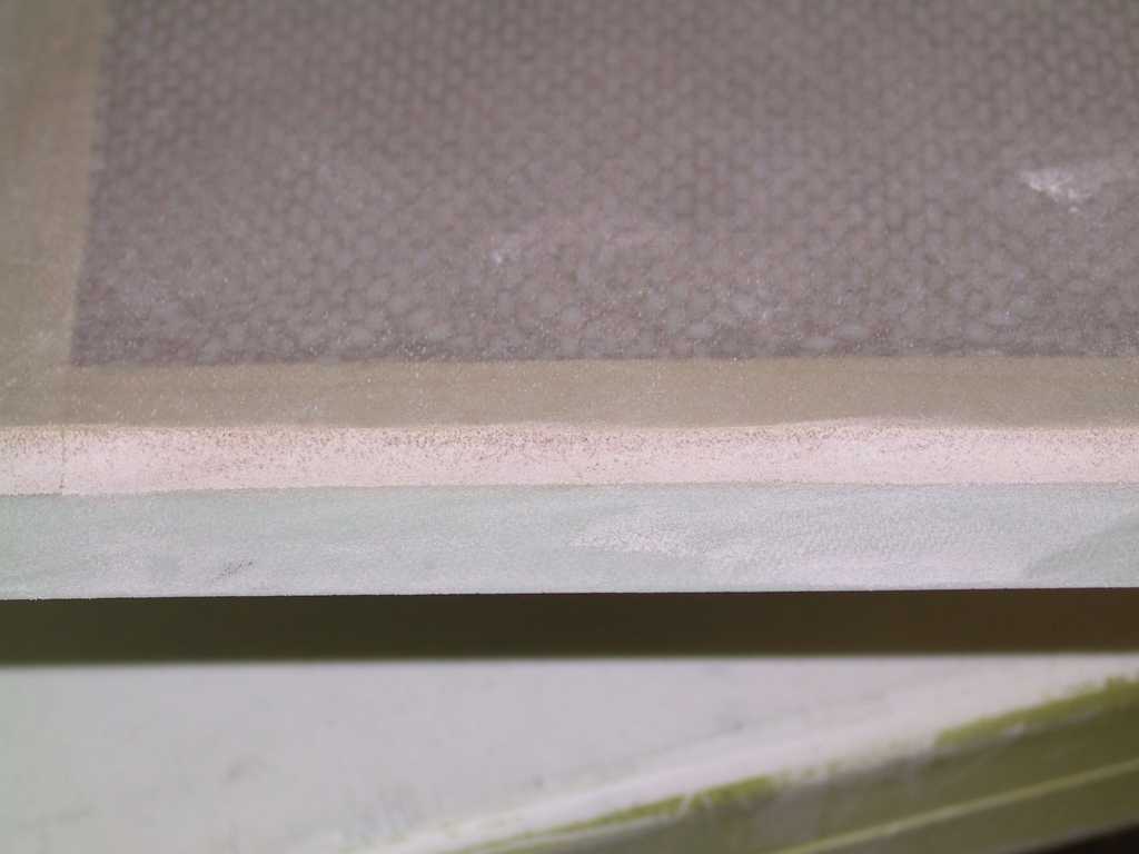
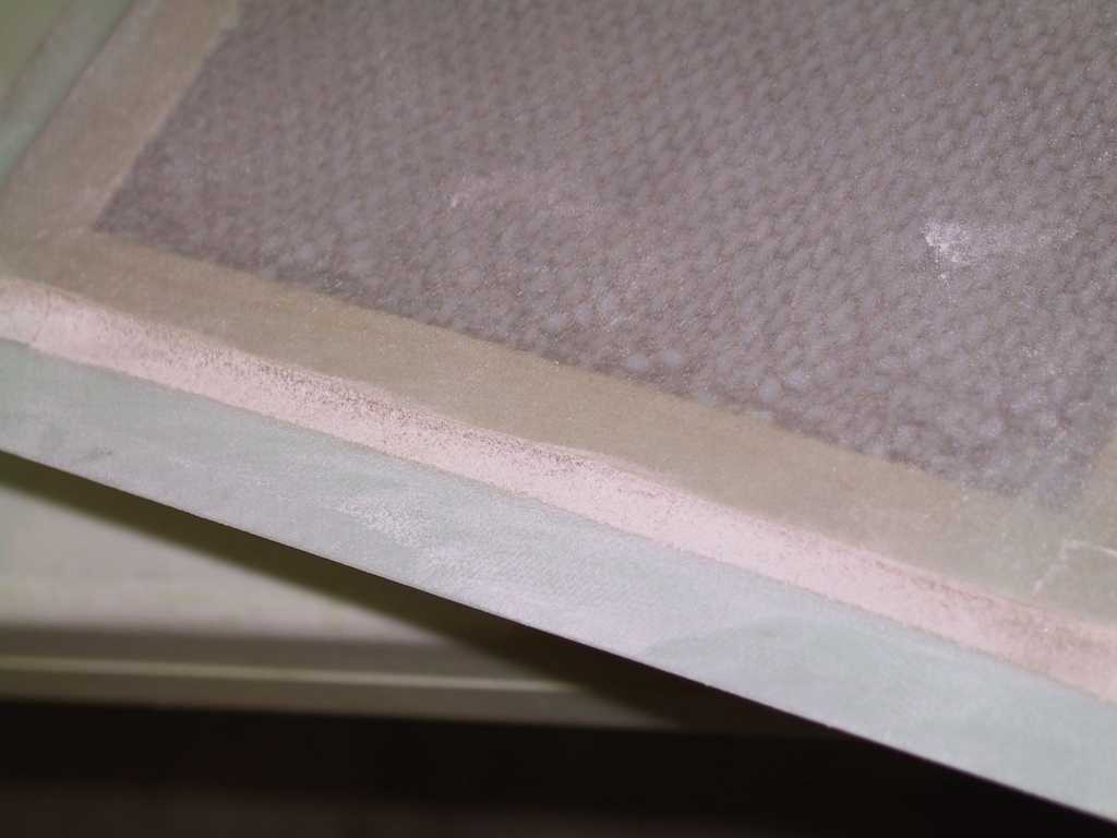
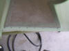
The red line shows where I have to grind down the foam core both on the
left and right sides of the bottom of the cowl.
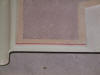 
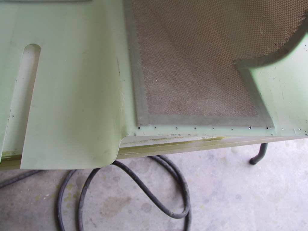
Post grinding shot, before an epoxy coating is applied.
 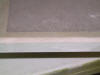 
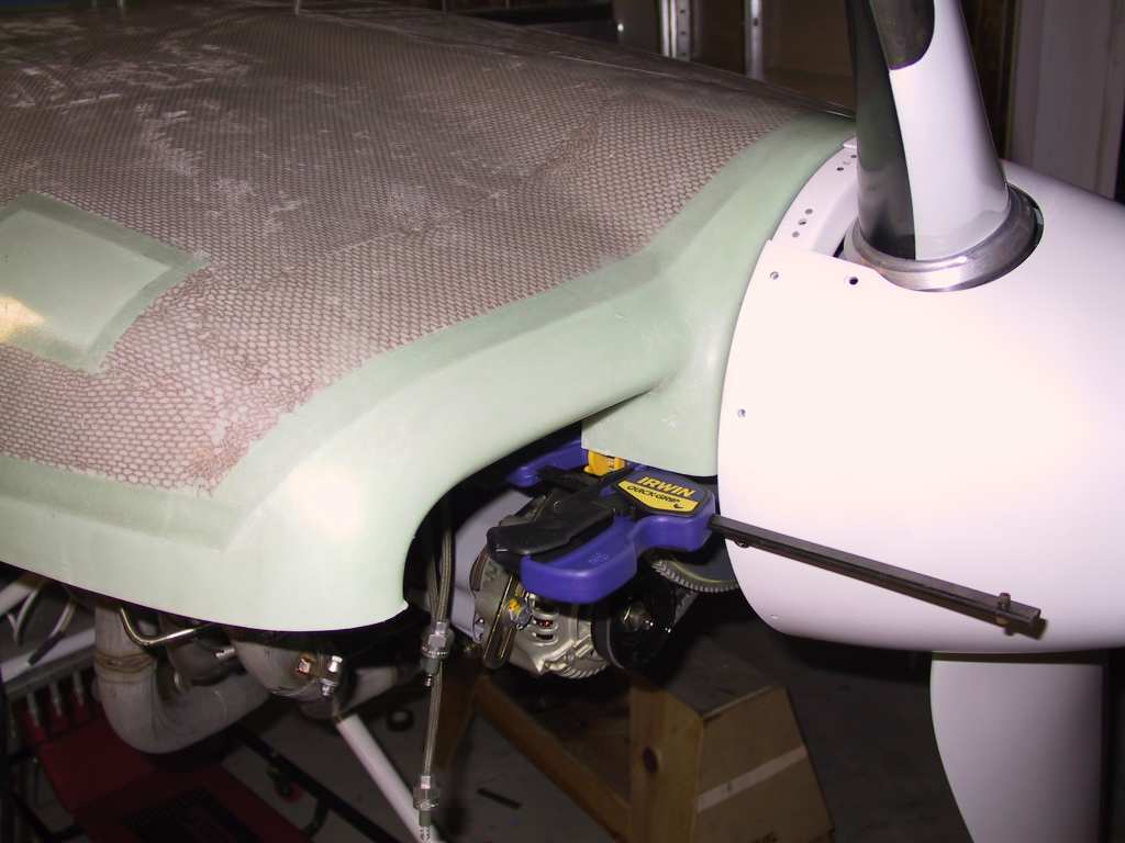
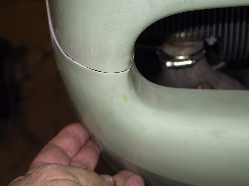
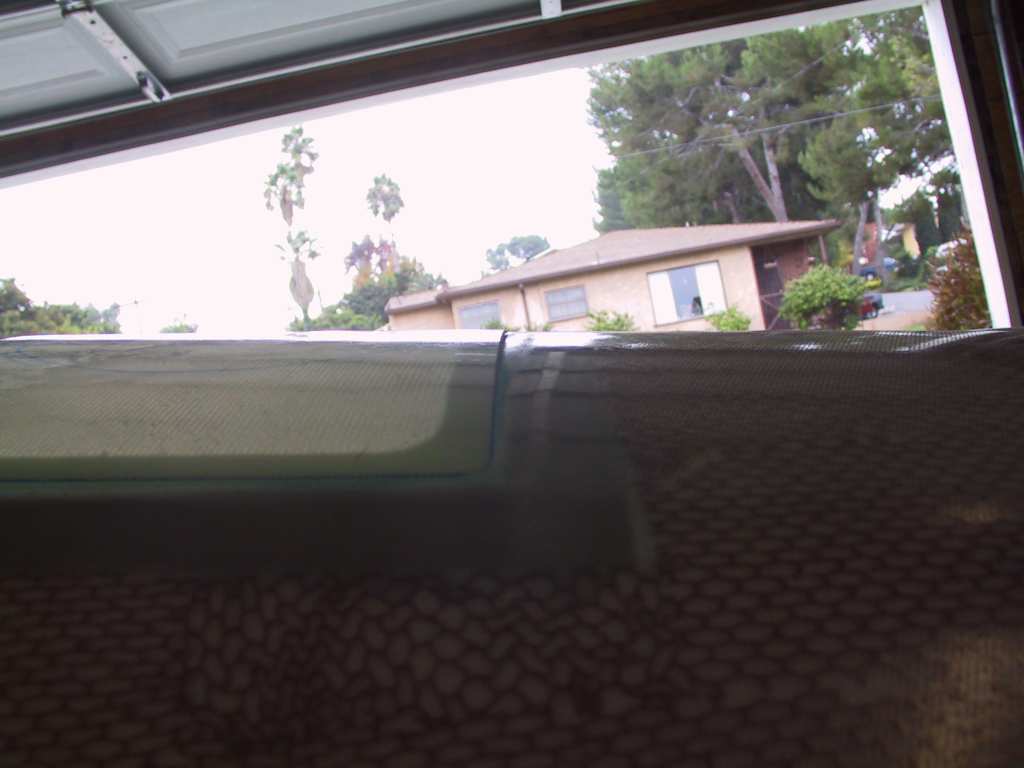
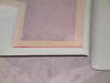
Live and learn. Here's what it looks like now. And the gap
between the upper and lower cowl is perfect this time. This is a whole
lot of work. I used a very small file and went along making sure the
gap was just so. In fact you can leave the upper and lower cowls on
while sanding/filing. Just pull the lower cowl sides out a bit and
file. Easier than constantly removing and replacing the cowl.
  |
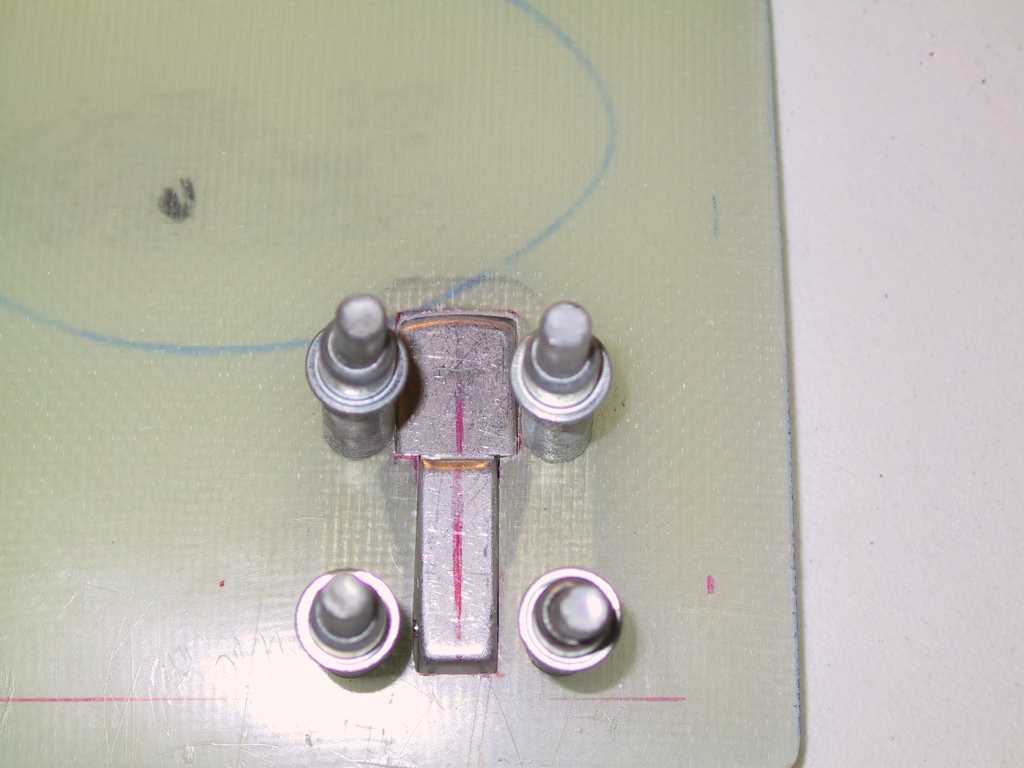
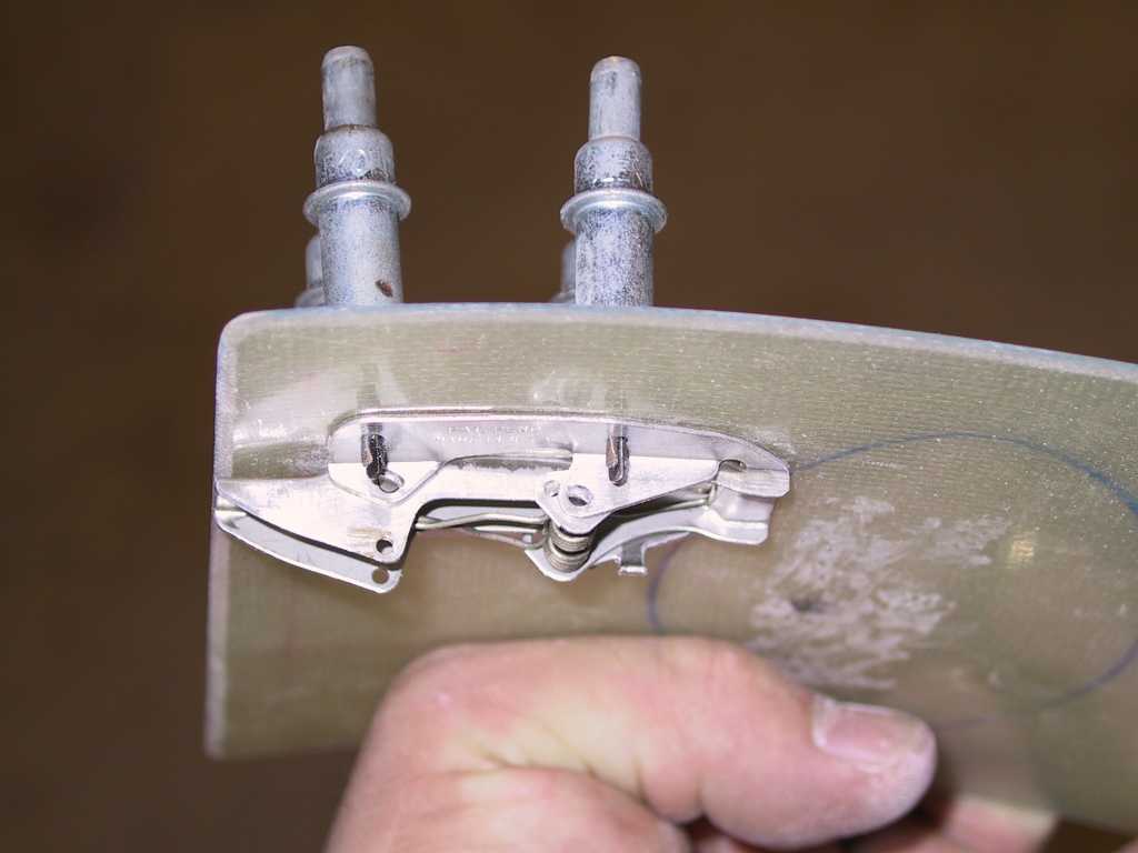
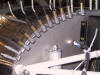
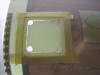
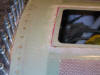
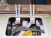
| 12/4/04 |
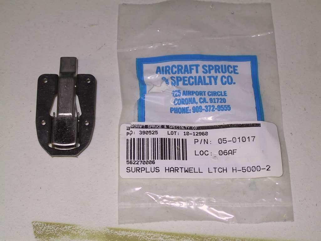
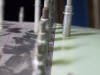
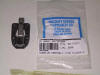
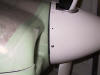
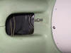
More work on the oil door. I placed the Hartwell
5000-2 latches behind the door and held it up to the light, tracing an
outline of the latch as a guide for cutting the holes. Started the
cutouts with a unibit and then slowly filed with a jewelers file until the
cutouts were perfect. I decided to use two latches since I've heard of
some oil doors lifting up in the negative air pressure zone that they are in
on the cowl. Maybe this will help.
  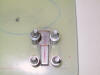 
These latches are just a tad lower than the surface of the door, no
biggie, works for me.
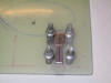
You can't see from these pictures but both latches, although the same
manufacturer and part number, were not entirely the same. One had a
patent pending stamp and the other had a patent number imprinted on the
latch. Problem is that the latching area or latching finger gap was
inconsistent between the two. Which means that one would grab properly
when latched and the other would have a small gap. I'm going to order
another and see which one I get back and match it with one of the ones I
already have so they are symmetrical.
   |
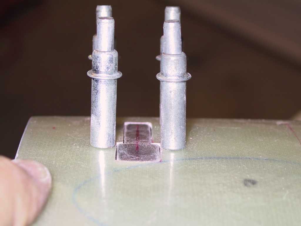
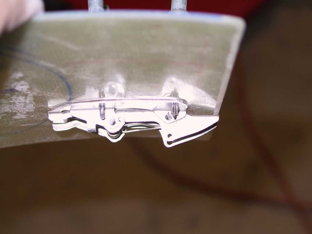
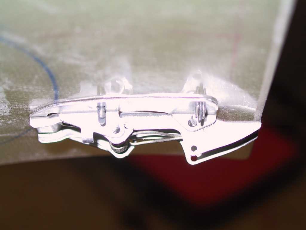
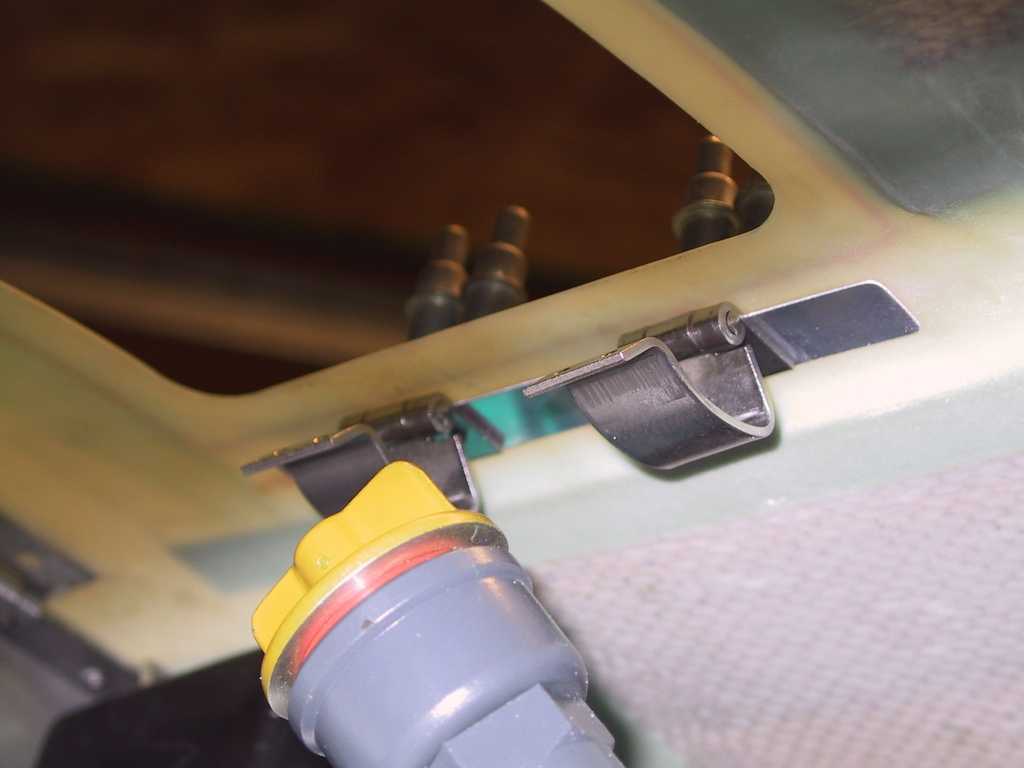
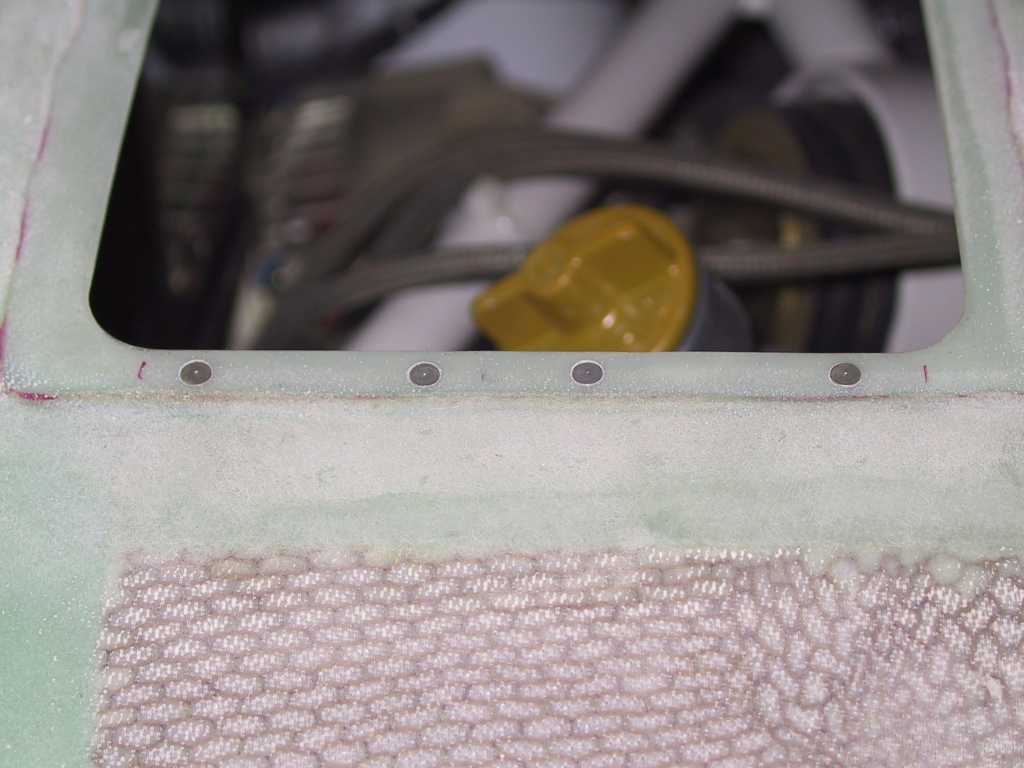
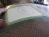
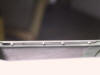
| 12/6/04 |
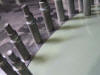
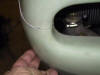
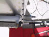
Here's a shot of the hinges nicely snuggled up into the
recess I cut out.
  |
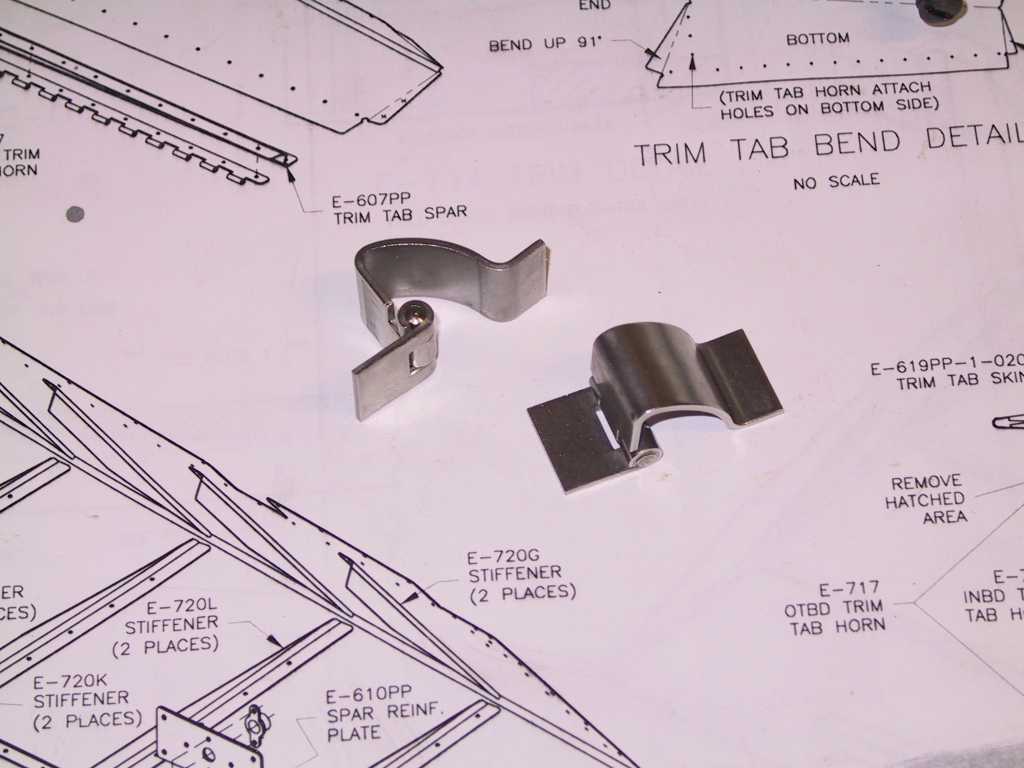
| 12/7/04 |
I saw that Dan had used these hinges. I bought a pair
from McMaster Carr. They're pretty nice but there is a lot of slop in
the mechanism. Hopefully that won't make much difference when two of
them are on the oil door.
One thing to note about the placement of these hinges, they are offset
hinges so be careful where you place them. I ended up having to shave
a portion of the door off on the side where the hinges are located in order
to open the door to 90 degrees. Because of that I decided to fill the
area around the door with flox and epoxy and build up that area a tad all
the way around. The recess that comes with the cowl isn't very deep.
I suppose that it's better for the door to stick up a bit anyway so that it
doesn't get sucked up because of an exaggerated negative pressure area due
in part because the door is lower than the cowl skin. I guess I'll
find out...
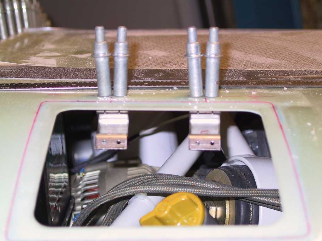
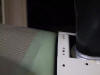
I placed an aluminum backer strip where the hinges get riveted on just in
case. I've left the hinges just clecoed on for now.
  |
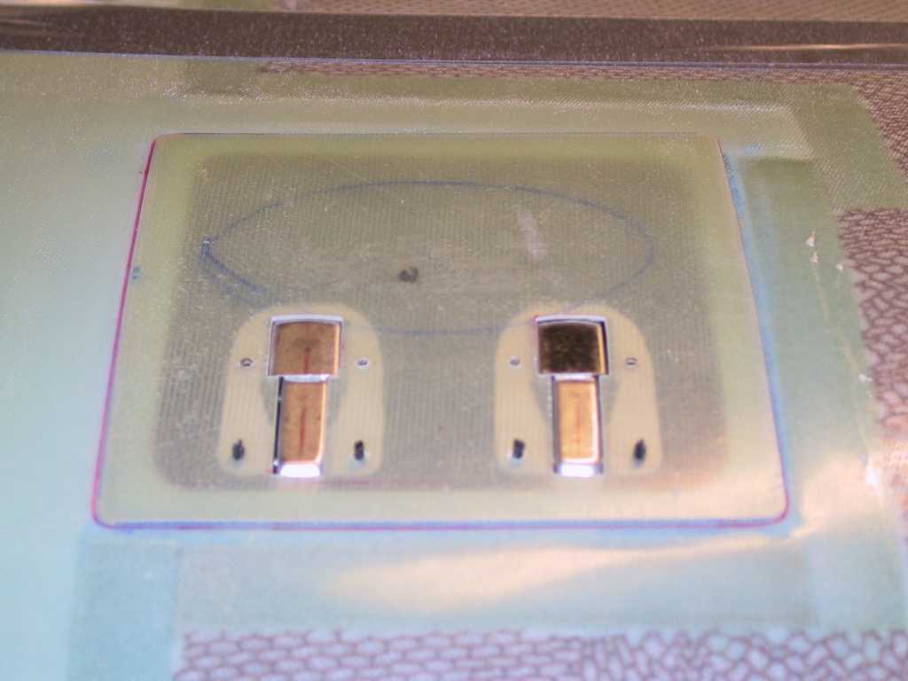
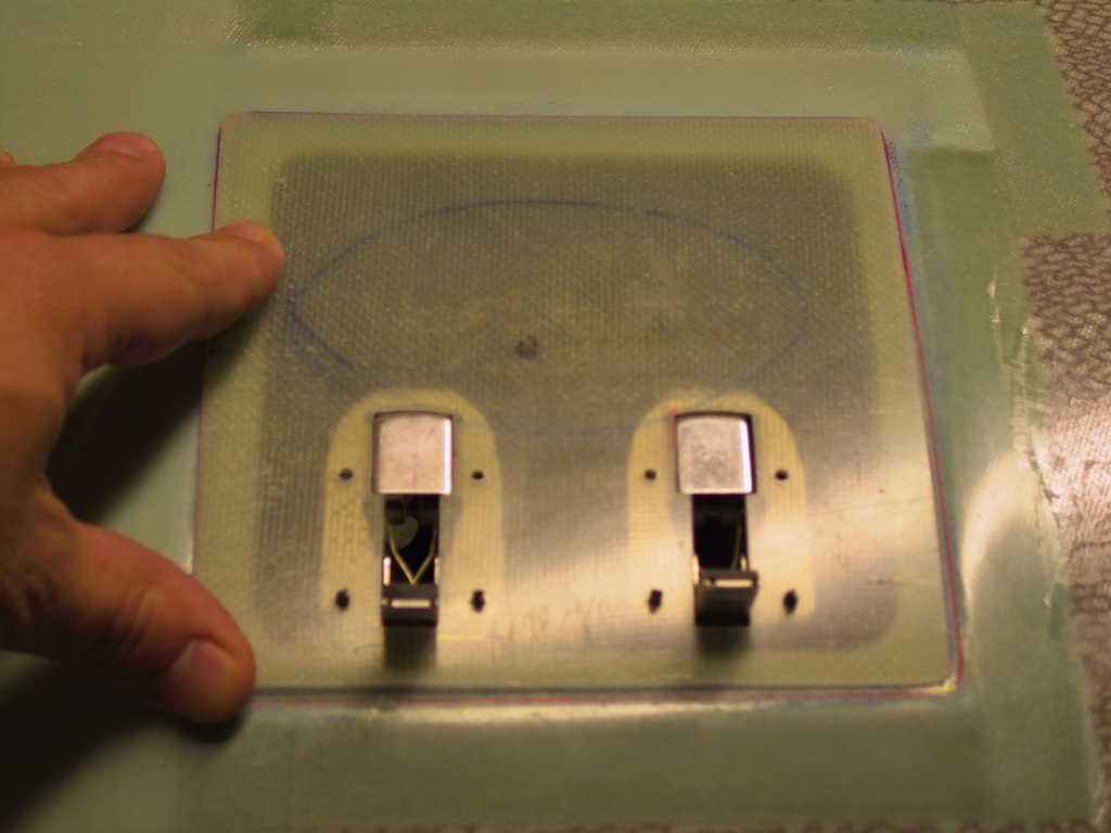
| 12/14/04 |
I placed a backing strip where the latches will close on the
oil door. Again, just in case. And, I received the third
Hartwell latch and guess what, it had a patent number on it and it matches
the other with a patent so I'll use those two and toss the third into my
spares bin. Be sure to check your for matching patent or patent
pending markings, they are different.
  |
| 12/21/04 |
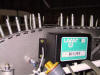
Dave Bristol came by today for another Tech inspection.
I slathered him with a zillion questions about this baffle stuff. And
this morning before the inspection (which I passed I assume) I got out the
filtered air box (which shall henceforth be named +junk+) to see how it will
fit. Well, it doesn't. The plans say it will only fit with a
Lycoming Skytech starter, which I have, and it still doesn't fit.
Even if it did fit around the starter, it's too wide.
Thirdly, the filter is larger than the baffle floor into which it's
supposed to sit.
Time to plan a new approach. Ok, I need filtered air. You
never know when you are going to fly into an unimproved strip. I also
would like ram air. Not that you *really* get anything more with ram
air. Here's some Ram Air reading...
Marketers
just can't resist it. Ram air! The words themselves summon up images of
rushing wild beasts, or of secret military aircraft operating on futuristic
principles.
Unfortunately, on snowmobiles, ram-air is as functional as tail fins were on
cars of the ’60s.
What is it? Ram air just means using a forward-facing air intake to
gain some extra intake pressure. We have all, as children, felt the pressure
of moving air on our hands when we held them out the window of the family
car. When moving air is brought smoothly to rest, the energy of its motion
is converted into pressure. Motorcycles went through a "ram-air" period in
the early 1990s, during which street bikes were equipped with the
forward-facing "rocket-launcher" engine air intakes seen on many road-racing
machines.
While it's appealing to imagine the forward velocity of a snowmobile
being converted into free supercharge, the actual air pressure gain is
extremely small at snowmobile speeds. For example, at 150 mph, the pressure
gain when air is efficiently brought to rest is 2.75 percent. Because this
is a dynamic effect, it is proportional to the square of the air velocity.
At a more realizable snowmobile speed of 75 mph, the effect (again with 100
percent efficient conversion of velocity into pressure) will be only
one-quarter as great — that is, just under seven-tenths of one percent.
In fact, velocity energy is not converted into pressure at 100 percent
efficiency. A figure of 75 percent efficiency is usual, which reduces our
notional ram-air gain at 75 mph to one-half of one percent.
Therefore, at normal snowmobile speeds, ram air is a myth. However,
something much more interesting lies behind it, ignored by the advertiser's
busy pen. That something is air box resonance.
In order to implement ram air, the carburetors or throttle-bodies of
our engine must seal to an air box whose volume is large enough that the
intake cycle of one cylinder cannot pull its internal pressure down
significantly. Box volume is typically 10-20 times the engine's
displacement. Then the forward-facing air intake is connected to the box.
When this assembly is tested on the dyno — even without an external fan to
simulate the high-speed rush of air past the intake — it is discovered that
the engine's torque curve is greatly altered, with new peaks and hollows.
Why? The answer is air box resonance. If you hold the mouth of an empty
bottle near your open mouth as you loudly hum scales, you find that at
certain “hum frequencies” the bottle reinforces your humming, which becomes
louder. What is happening is that the springy compressibility of the air in
the bottle is bouncing the slug of air in the bottle's neck back and forth
at a particular frequency — higher if the bottle is small, lower if it is
larger. Your humming is driving a rapid plus-and-minus variation of the air
pressure inside the bottle.
The same thing happens inside a resonant air box. The volume of air in
the box is the “spring” in this kind of oscillator. The mass of air in the
box's intake pipe is what oscillates. The “humming” that drives the
oscillation is the rapid succession of suction pulses at the carb or
throttle-body intakes. If the volume of the air box and the dimensions of the
intake pipe(s) are correctly chosen, the air box can be made to resonate very
strongly, in step with the engine's suction pulses. The result, when this is
done correctly, is that the engine takes air from the box only during the
high-pressure part of its cycle, while the box refills from atmosphere
through its intake between engine suction pulses. This produces a useful
gain in torque.
Using this idea, motorcycle engines have been able to realize torque
increases, in particular speed ranges, of 10-15 percent. In race engines, it
is usual to tune the air box to resonate at peak-power rpm to increase top
speed. For production engines, it is often more useful to tune the box
resonance to fill in what would otherwise be a flat-spot in the torque
curve, resulting in smoother power and improved acceleration.
Early resonant air box systems used long intake pipes that terminated
in forward-facing intakes. More recent designs do not connect the ram-air
pipe to the box at all, but terminate it near the air box entry. The actual
entry pipe is a short piece of tubing with bellmouths on both ends. This is
done because (a) the potential gain from actual ram air is too small to
worry about, and (b) it's easier to tune the air box with a short tube.
Where vehicle speeds are very high, gains from ram air are
significant. This was discovered by Rolls-Royce in the late 1920s as the
company developed its R Schneider Trophy air racing engine. At speeds above
300 mph, it was noticed that the R’s fuel mixture leaned out enough to cause
backfiring. When the mixture was corrected for ram-air pressure gain, the
engineers realized they had a "free" source of power. At 350 mph the gain
from ram air is almost 15 percent. Similar mixture correction is necessary
when ram air is used on drag-race and Bonneville cars and bikes.
Intuition suggests that a forward-facing intake made in the form of a
funnel, large end foremost, should somehow multiply the pressure of the air,
resulting in a much larger pressure gain at the small end. Sadly, intuition
is wrong. In order to convert velocity energy into pressure, the air has to
be slowed down, and this requires a duct that widens rather than narrows.
Next time you fly on a commercial airliner, note that its engine intakes
widen as the airflow approaches the compressor face. Such widening passages
are called diffusers, and they are universally used in the conversion of
velocity into pressure.
Language often plays tricks on us — especially when language is used
by product advertisers. "Ram air" sounds much more appealing than "resonant
air box." Nevertheless, it is air box resonance that actually generates a
significant power gain. At snowmobile speeds, ram air is just words.
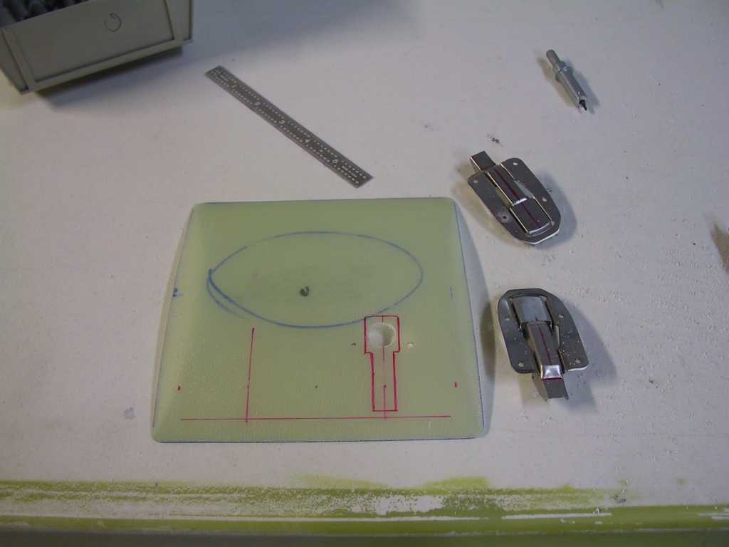
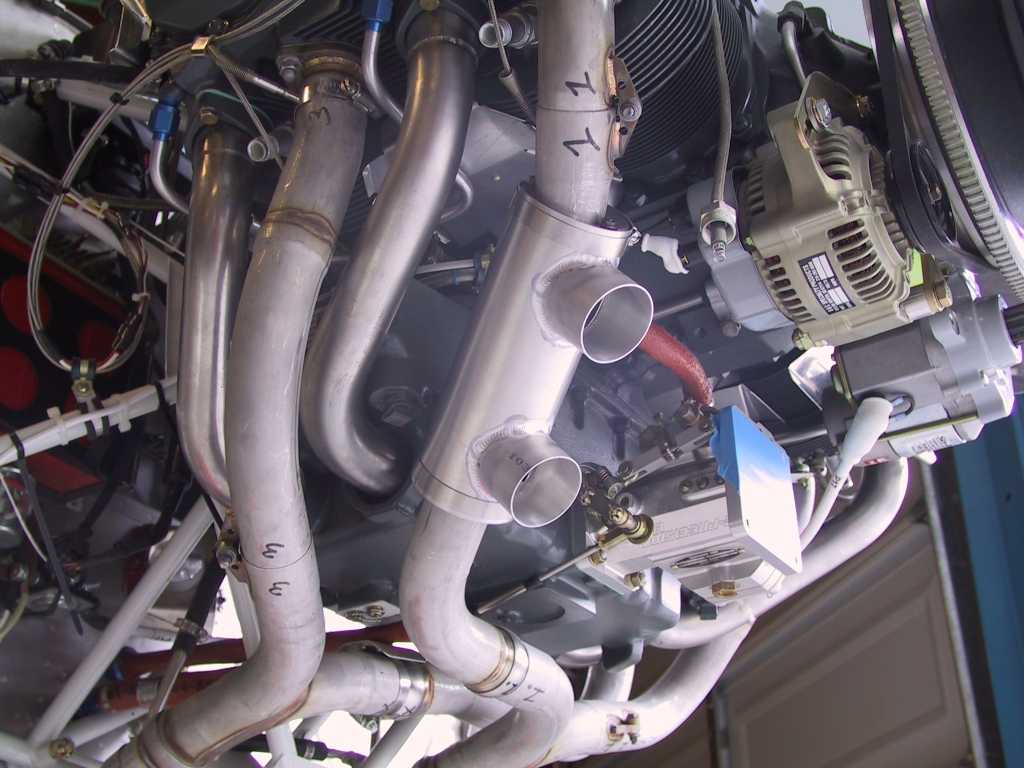
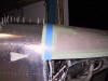
So my choice is probably going to be some sort of oval opening in the
cowl just below the spinner on the lower cowl. I will probably angle
the opening about 10 degrees or so above the horizontal since that's
probably how the wind is moving across the cowl at that point. The
opening should be smaller than the tube itself to slow the air as much as I
can. Problem with trying to build anything of any size is that there
just isn't any room. I probably only have 4 inches from the cowl to
the intake. The intake should also stick out about 3/4" above the skin
of the cowl to minimize as much as possible scarfing up turbulent airflow.
I need to think more about this...
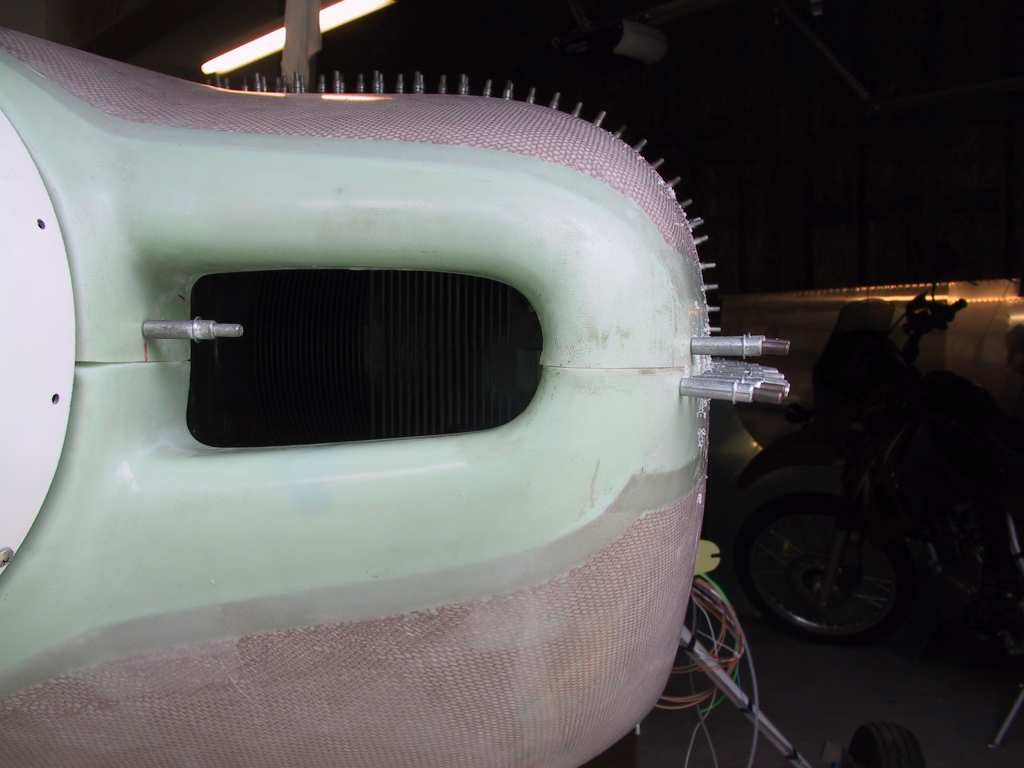
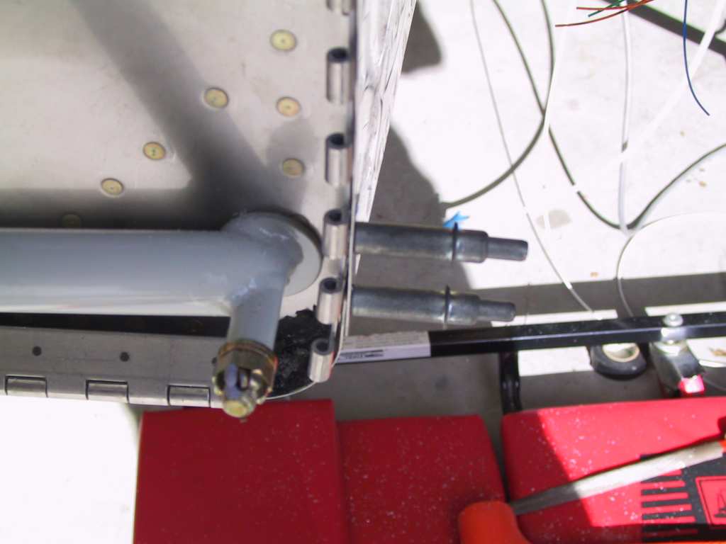
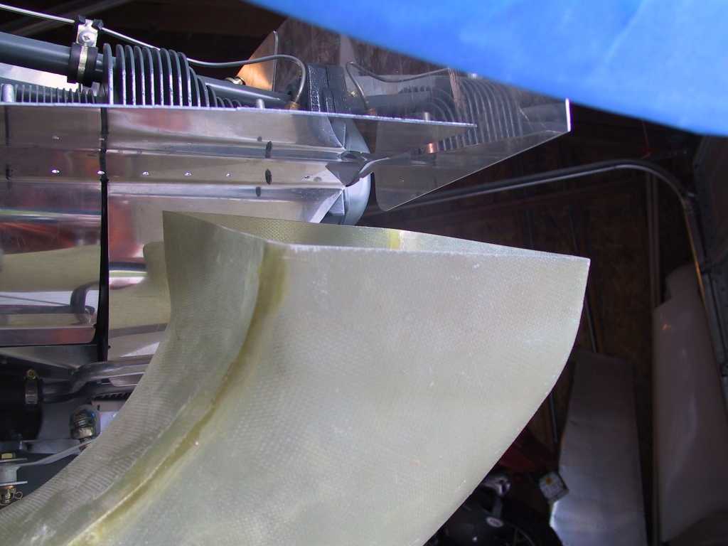
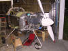
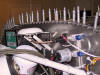
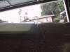
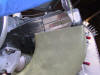
And finally, I mounted the heat exchanger I bought from Vans recently.
This is about the only place it will fit on my engine/exhaust. It sure
would have been nice if the input and output were opposed by 90 or 180
degrees. I may split it and have it rewelded with a 90 or 180.
Let's first see how the scat tubing is going to run like it is now.
 |
|
12/22/04 |
Today I spent some time considering what I want to do with
regards to the ram air and the filtered air. After consulting with Dan
via email I spoke with the guys at Airflow Performance about obtaining one
of their Y valves. I'm now thinking that a oval snorkel on the cowl is
the way to go. The filtered air may come from two choices; 1) get a
smaller rectangular K&N filter that will fit into the left floor inlet
baffle or 2) place a conical K&N filter on the Y valve and leave it in the
bottom cowling. Number 1 poses the additional problem of cutting the
floor inlet, there's not much room there. But I would get cold air.
Placing the intake in the area below the engine give me the additional
advantage of having essentially carb heat, but that also affects
performance. But I'm leaning towards solution #2 right now. Now
I just have to find the proper Y valve. They have two that might fit;
FM-100 and FM-200. I have to measure my inlet to find out which one is
the best fit. Unfortunately both are long; 5.25 inches for the FM-100
and 6 inches for the FM-200. And both have different inlet (ID)
diameters. And on top of that I'm too lazy to go take off the lower
cowl and measure at this late time in the evening. I'll measure and
order tomorrow but It probably won't ship until after the holidays as they
are closed all next week due to Christmas. Oh well it's not a rush job
anyway... |
| 1/11/05 |
Well I guess it's finally time to get the lower cowl to
upper cowl hinge drilled. I made sure everything lined up and drilled
that sucker. I still haven't figured out how I want the hinge pin
secured. More thinking is required. I currently have no gap
between the upper and lower cowl. I will sand a small paint gap in
before securing the hinge to the lower cowl.
  |
|