| 7/10/04 |
Making steady progress. I wanted to get to the
interior painting this morning but I just wandered into more electrical
work. I've been really concentrating on getting all my wiring data
down pat. There's just so much information to process. Every
piece of equipment has specific and special requirement. And on top
of that it's been one month now and I still can't find the proper square
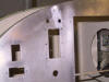
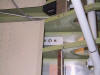
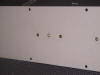
led illuminated pushbutton switches that I want. First I mounted the
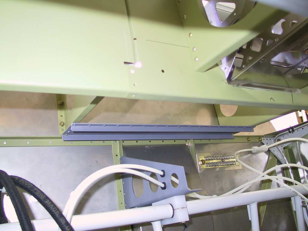
firewall/avionics/panel ground tab that I purchased from B&C. I
bought the 24/28 tab ground block. It's ok to have too many but
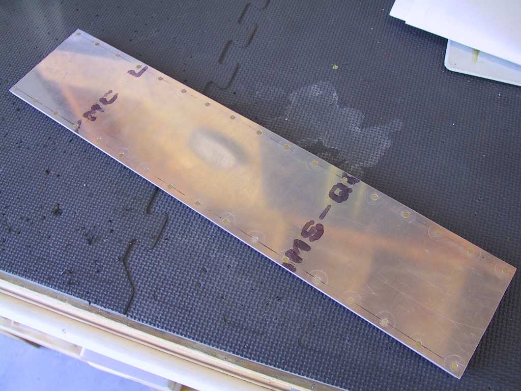
running short is not fun. I fabricated a stiffener plate. I
didn't rivet it to the firewall. But I did add a third bolt where it
seems one should be to keep it immobile. It's approximately where
Vans indicates it should be.
 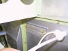  
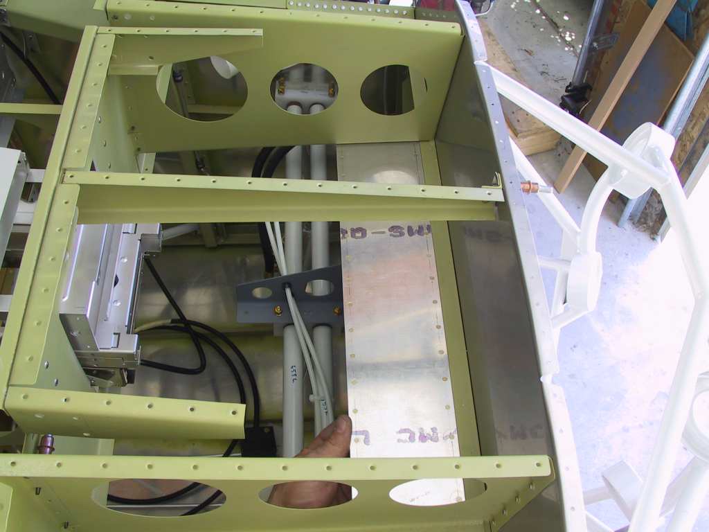
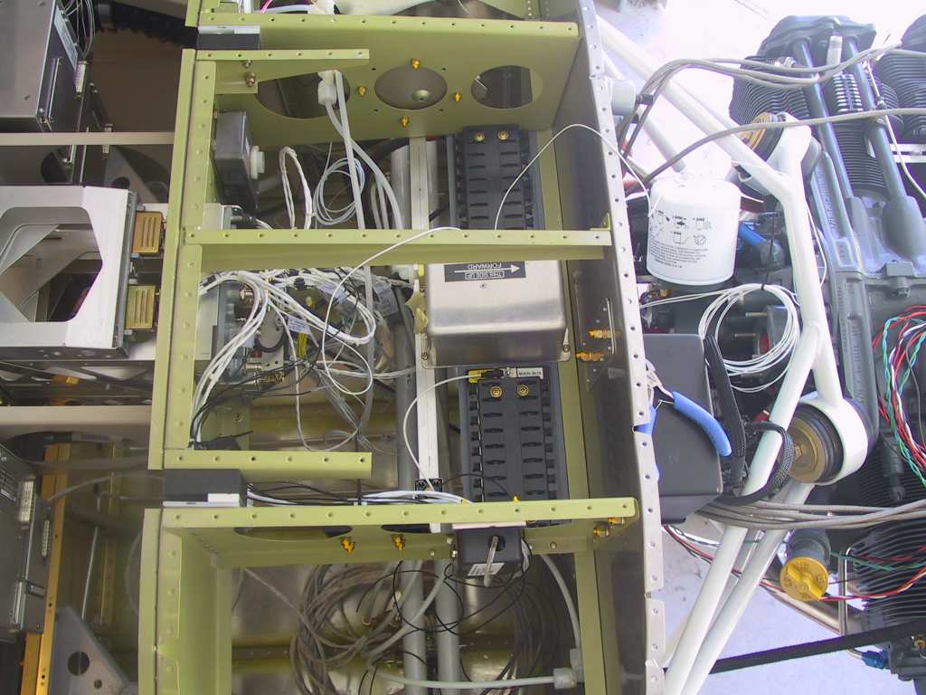
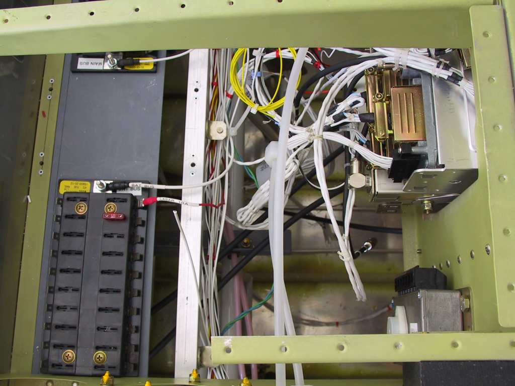
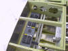
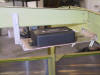
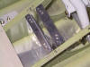
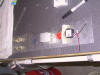
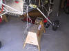
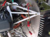
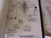
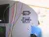
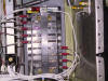
Next I decided to fabricate a small shelf to place the main, endurance
and battery busses. Most builders are mounting them vertically on
the sub panel. But what a waste, in my situation, I have these
awesome access panels. And If a fuse does blow I want to be not only
able to replace it but to see what I'm doing. I made a couple of
angles which would stiffen it up.
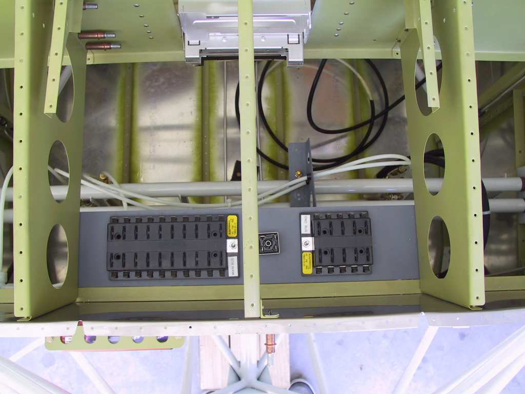
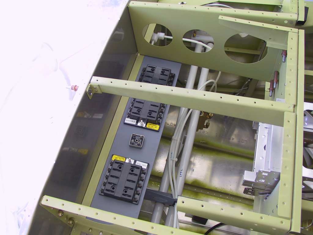
Test fit.
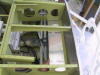
Rivet that sucker.
Here I only have the main and endurance sitting on the shelf, with the
diode, just for visualization.
  |
| 7/14/04 |
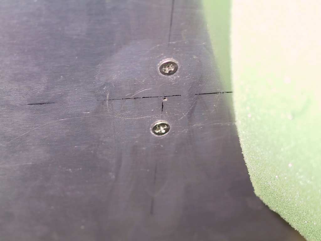
Next time to install the AOA Pro ports into the left wing.
I placed the top and bottom port 6 inches from the skin line at the spar
towards the leading edge. The top port is located 4.75 inches in
from the skin edge at the outer most wing bay. The lower is located
7.5 inches in board. I'm not happy with the screws they give you as
they stick up a bit and don't fit a dimple properly. I'll look for
better ones.
   |
| 7/23/04 |
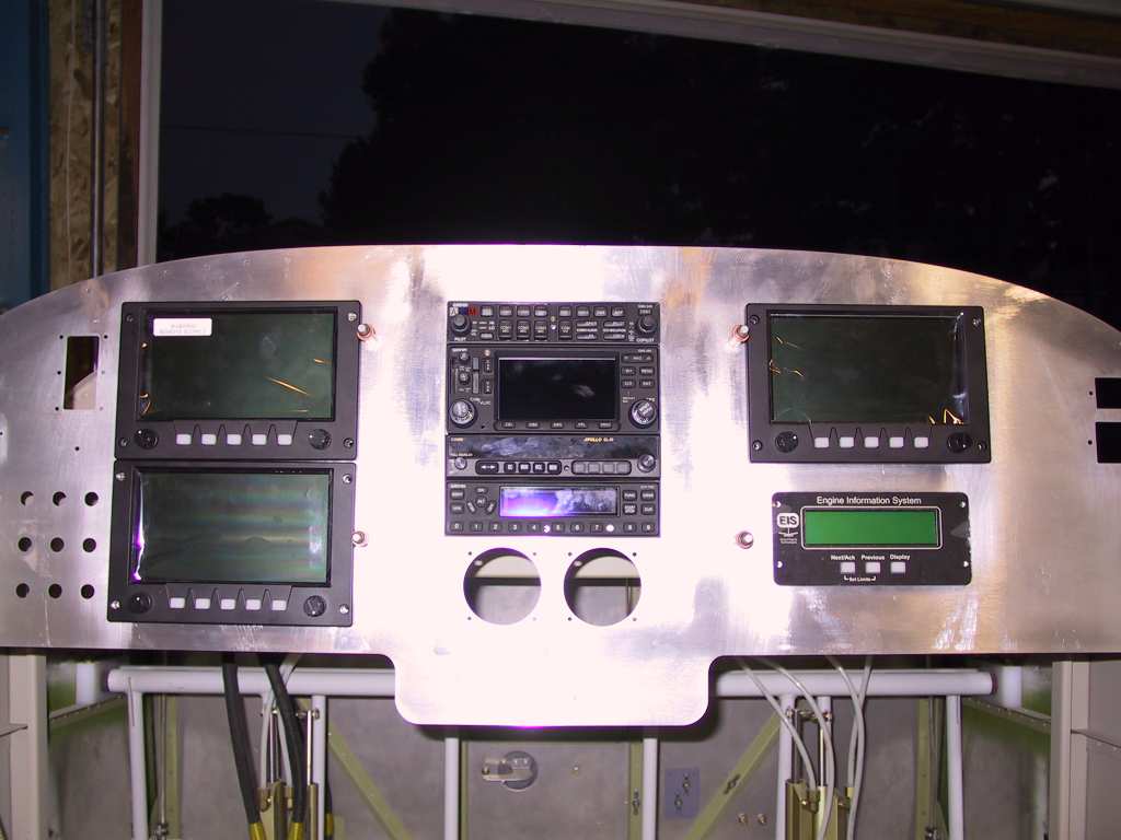
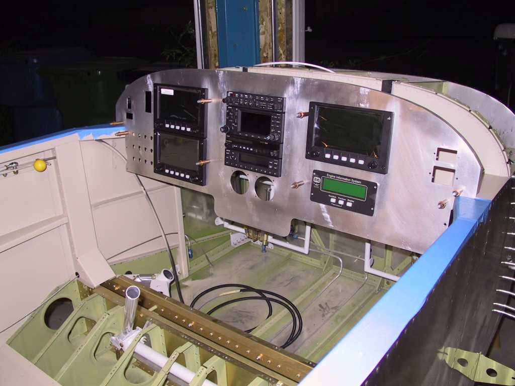
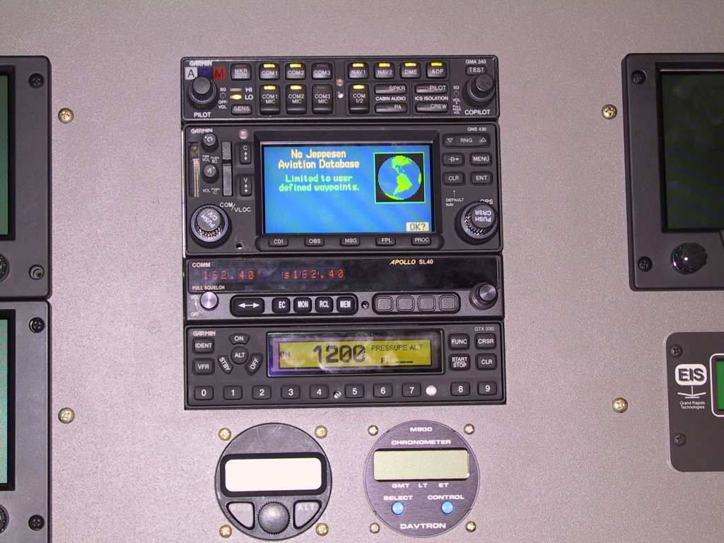
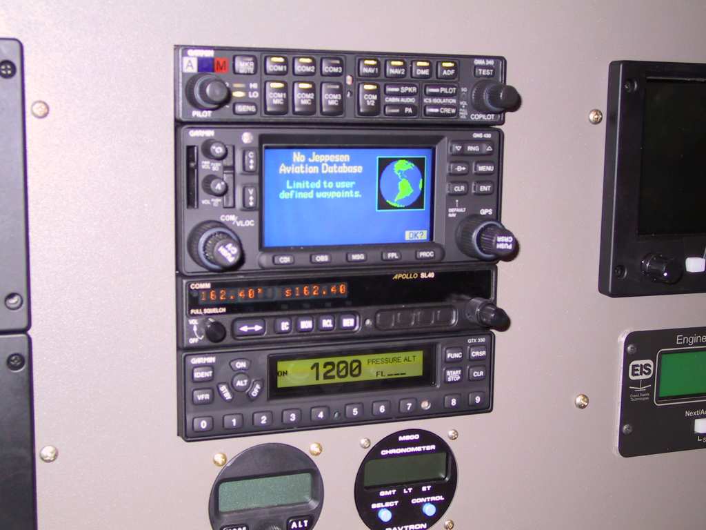
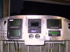
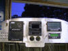
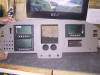
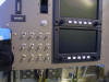
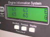
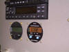
Test fit of instruments. I mounted some of the
instruments, very kewl. Nuf said bout this.
   |
| 8/6/04 |
Pops made some mounting angle for the AOA. Looks
great. I haven't figured where I'll put them yet.

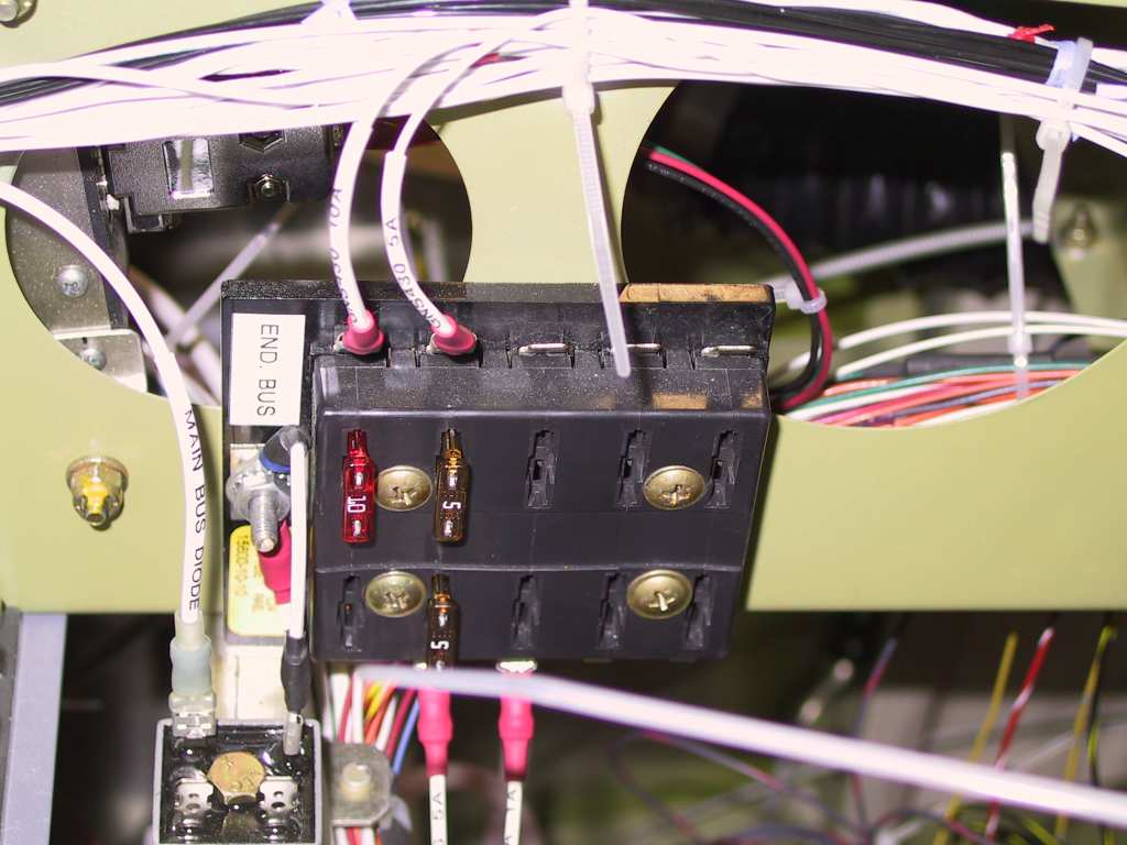
The E-bus is connected with the Master bus with the diode I purchased
from B&C.
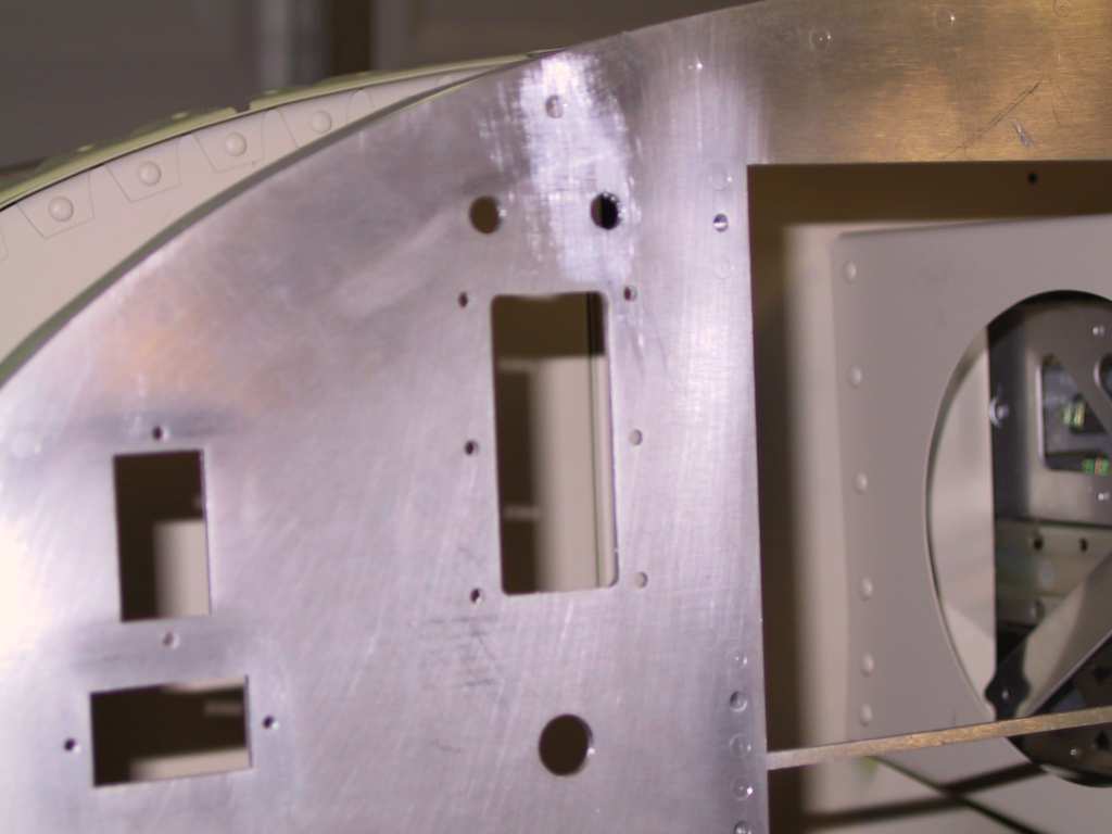
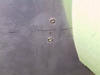
Drilled the two holes for the AOA momentary pushbuttons above the AOA
display.
 |
| 8/11/04 |
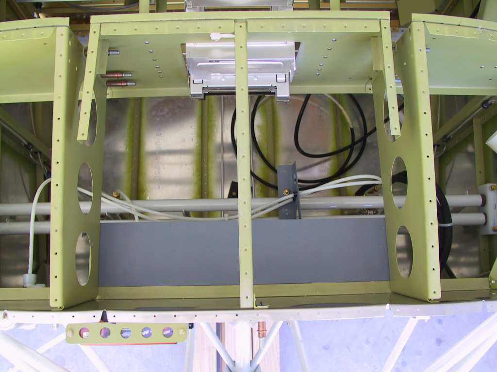
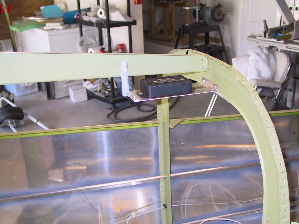
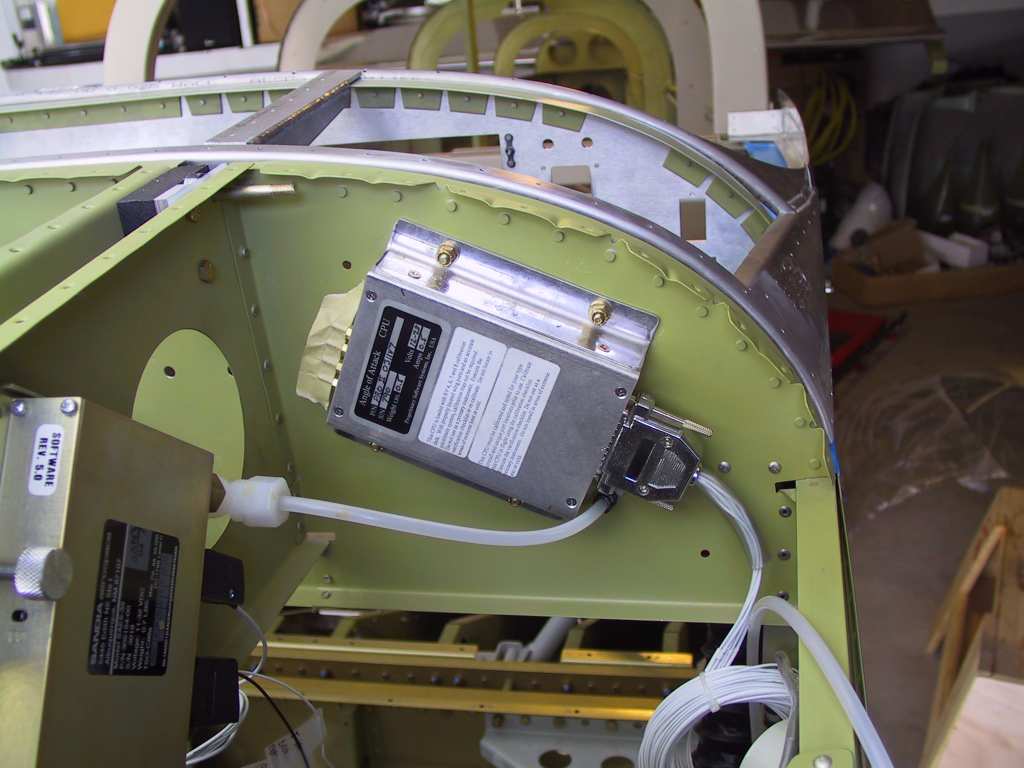
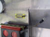
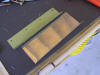
Fabricated a platform for the GRT magnetometer. When
I was at Oshkosh I spoke with Todd about the location for this instrument.
I didn't want to place it in the wing because getting the alignment for it
and the AHRS unit would be a pain. He recommended placing it at the
top of the F-707 bulkhead. Made a platform for it as shown.
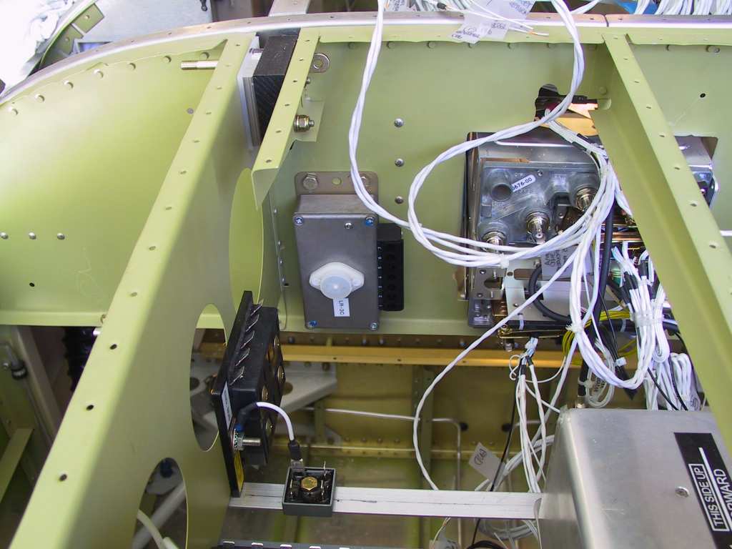
Next we installed the B&C LR3C-14 voltage regulator on the sub
panel
close to the avionics stack. The standby regulator goes on the
opposite side of the radio stack.
  |
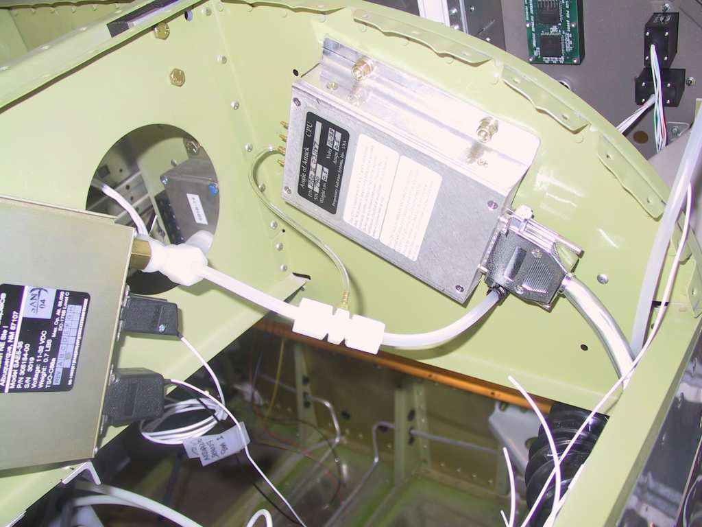
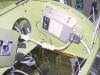
| 8/12/04 |
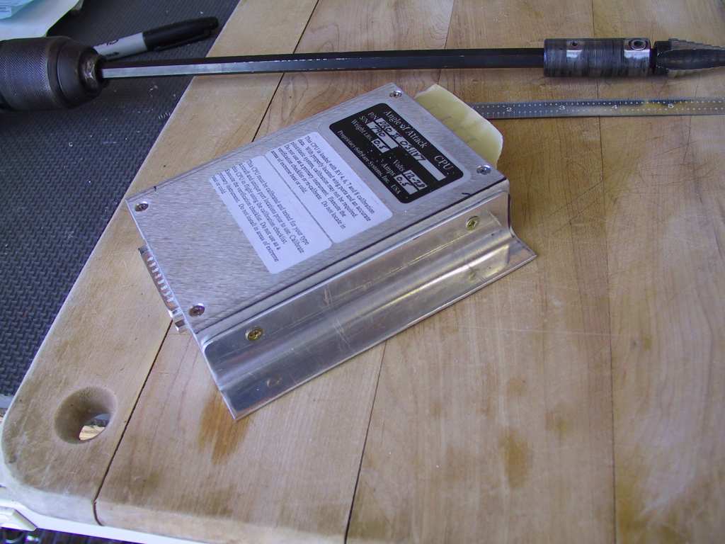
Didn't get much accomplished today except a lot of
thinking. It was just too damn hot in the garage to do anything.
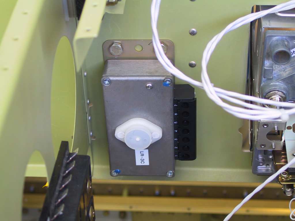
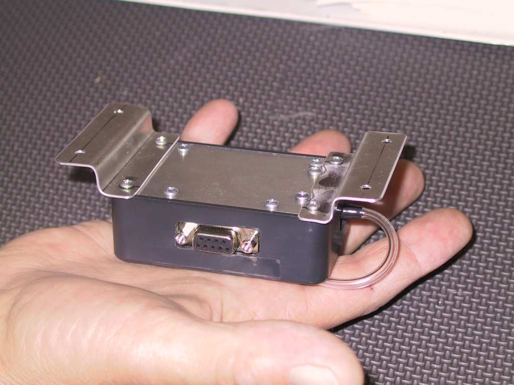
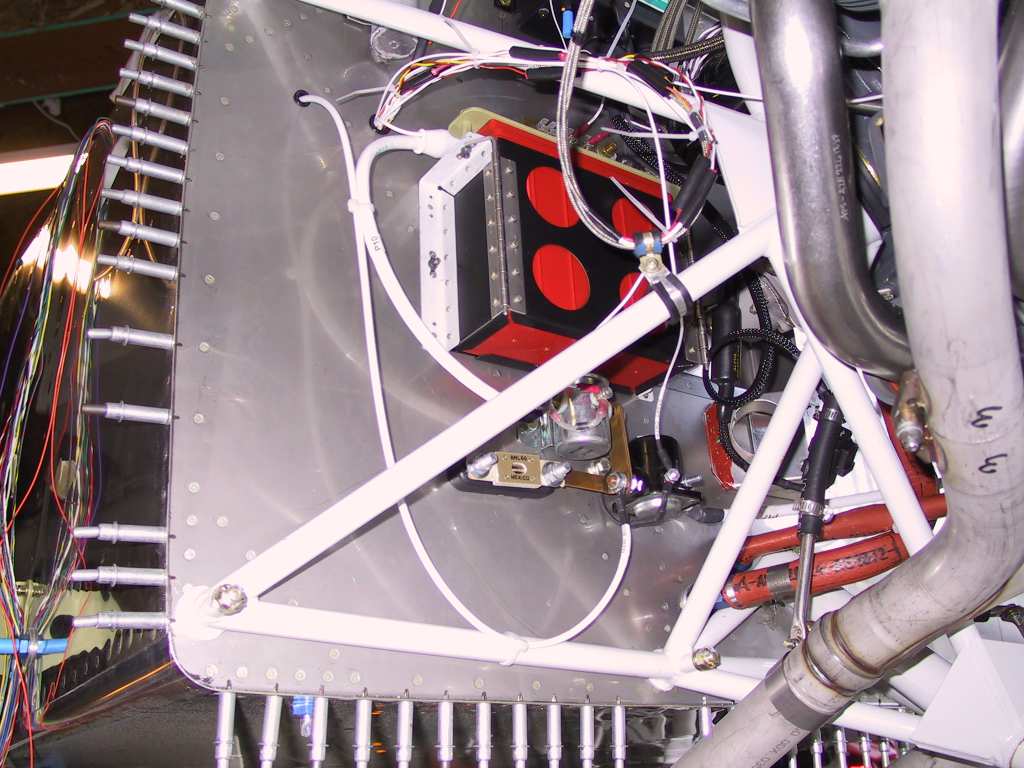
We did manage to install the AOA pro brain box onto the left front sub
panel.
All of my pitot and static tubes come through this area so it seemed a
natural.
 |
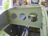
| 8/15/04 |
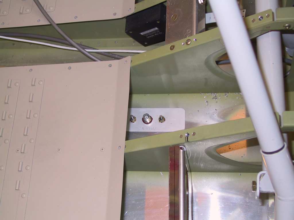
Mounted the primary COM antenna, a bent whip Comant
antenna on the belly of the fuselage, near the centerline just aft of the
F-706 bulkhead. Hade a backing plate about .5 inches larger than the
antenna base.
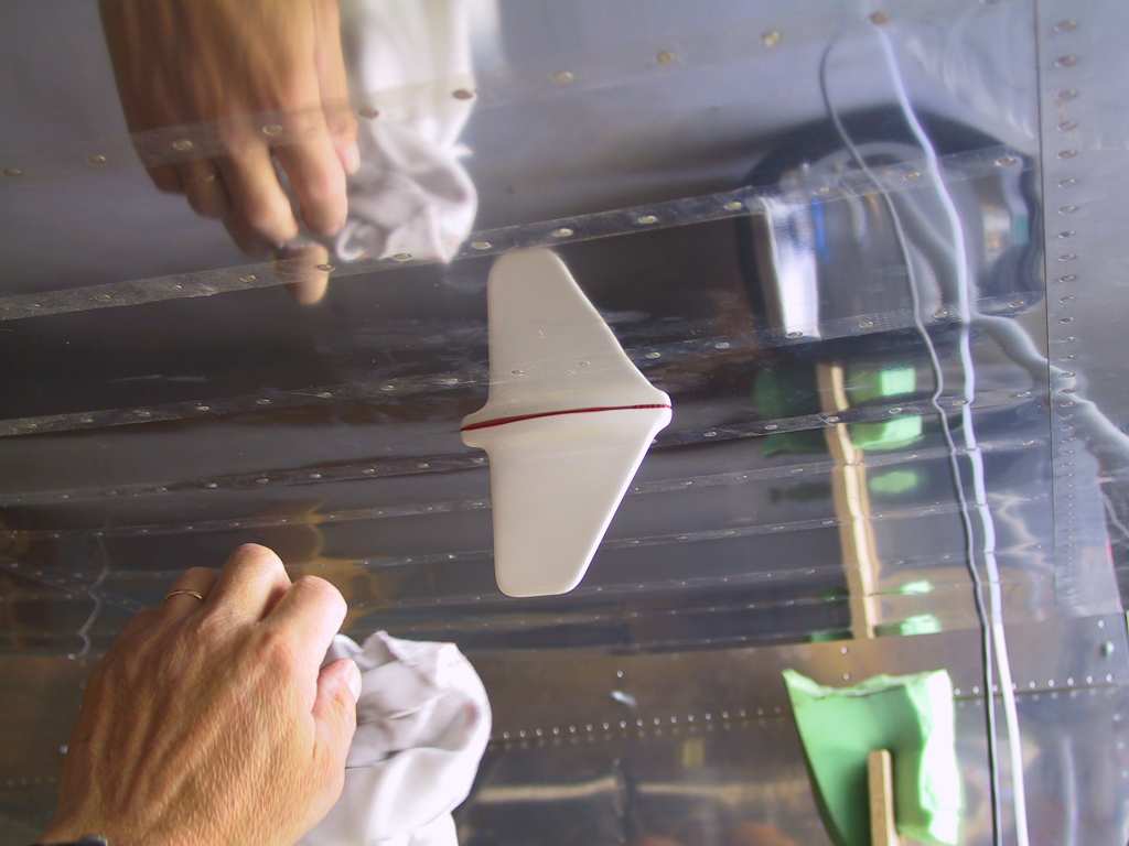
Mounted the transponder antenna, a Comant shark fin style just after
the center section in the first bay to the right of the centerline.
The Transponder antenna and Com are separated by several feet so there
should be no problems.

Now the real pain in the side. Mounting the crotch strap kit from
Vans for the 5-point seatbelt harness. Everything would work out
according to the plans if you use Vans (much more expensive) seatbelts.
I'm using Team Rockets belts. They are much better in my opinion.
Problem is that the webbing is thick than Vans so you have to take that
into consideration when mounting. I fabricated a wooden spacer plate
to fit the webbing thickness and use it between the front and aft brackets
to make sure it fits. Make sure the tops of the brackets are level!
If you move the aft bracket back a little from the plan specs and the
front bracket a little fore it fits nicely and you have plenty of hole
clearance for the nutplates on top of the brackets. My spacing was
3/8. Probably overkill but it works. Oh, and getting those pop
rivets in place, not to mention drilling the holes is a, lets just call it
tough. Do it then have a beer.
 |
| 8/16/04 |
My birthday. Didn't do anything but a lot of
thinking. |
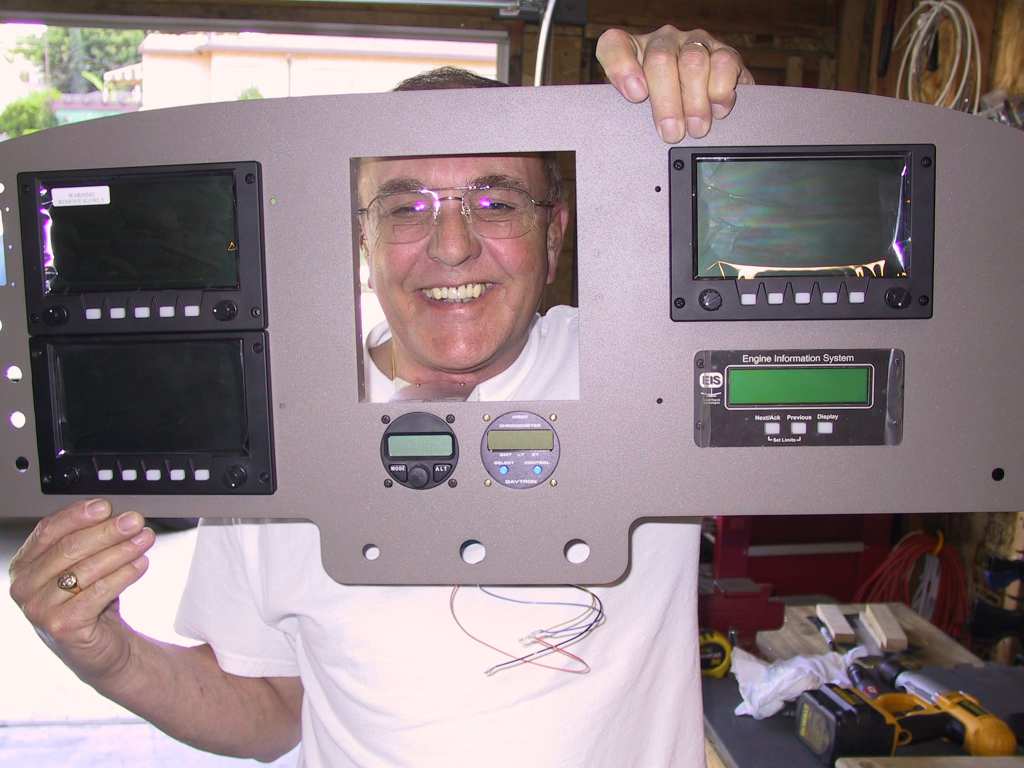
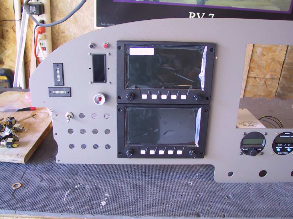
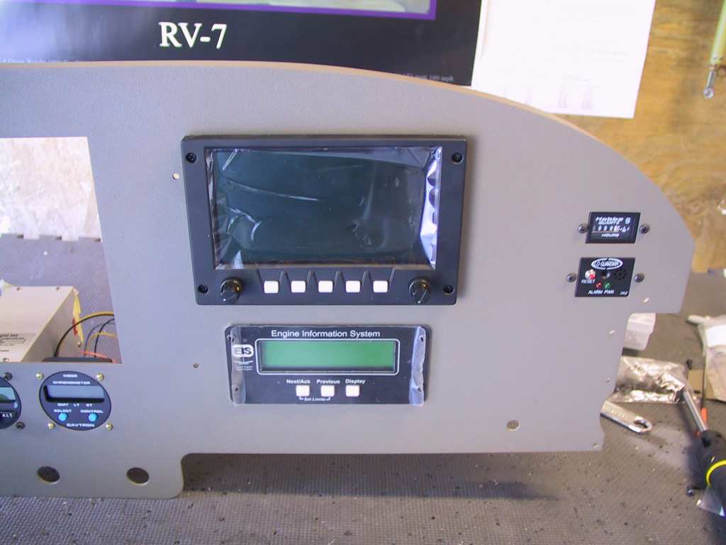
| 8/20/04 |
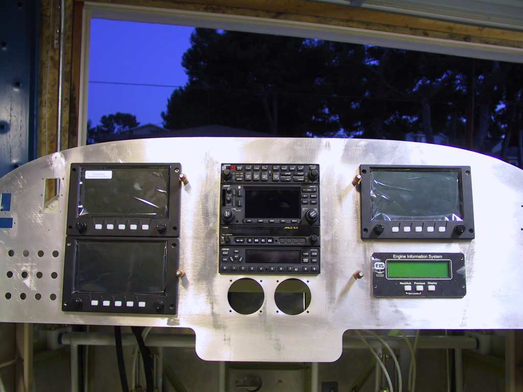
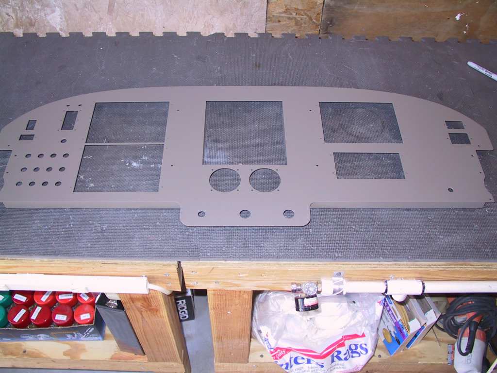
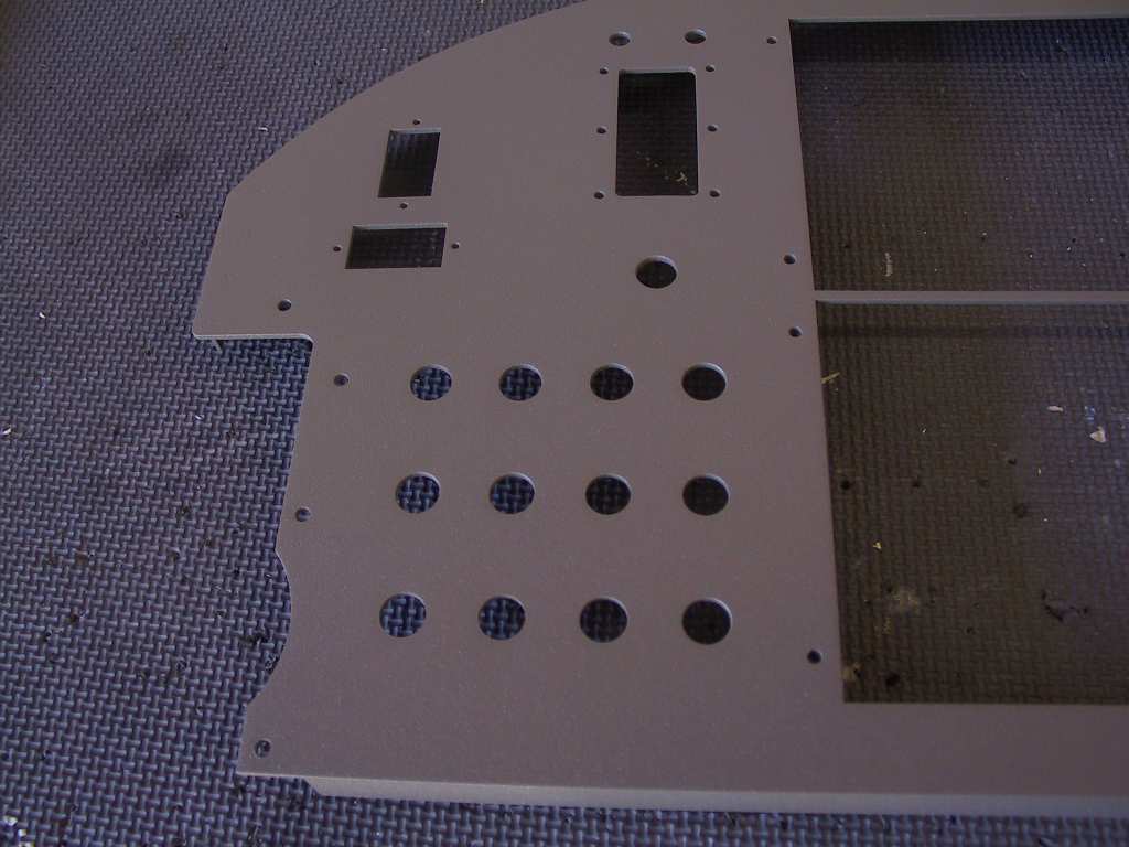
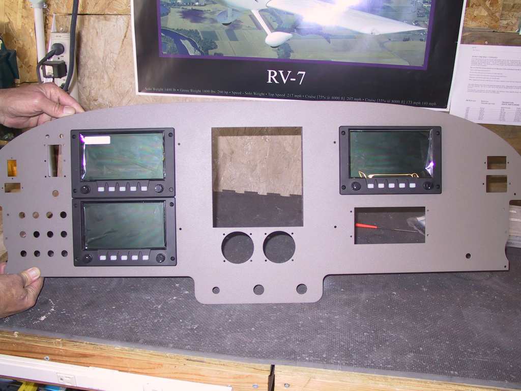
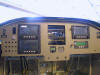
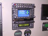
A few days ago we took the panel over to the powder
coaters, Vern's. This guy does all of the chroming for Chip Foose of
Foose Design. Chip is a notorious
hot-rod guy and has a TV show Overhaulin' on TLC network. I don't
trust my chrome or powder coating to anyone else. Anyway, I got the
panel back and what a thing of beauty. I couldn't resist sticking
some stuff in the panel and putting it into place temporarily. Dad
got into the action as well...
    |
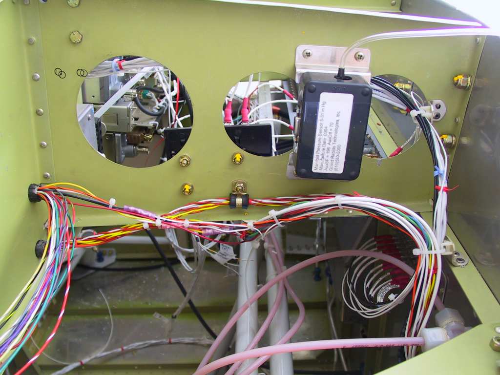
| 8/26/04 |
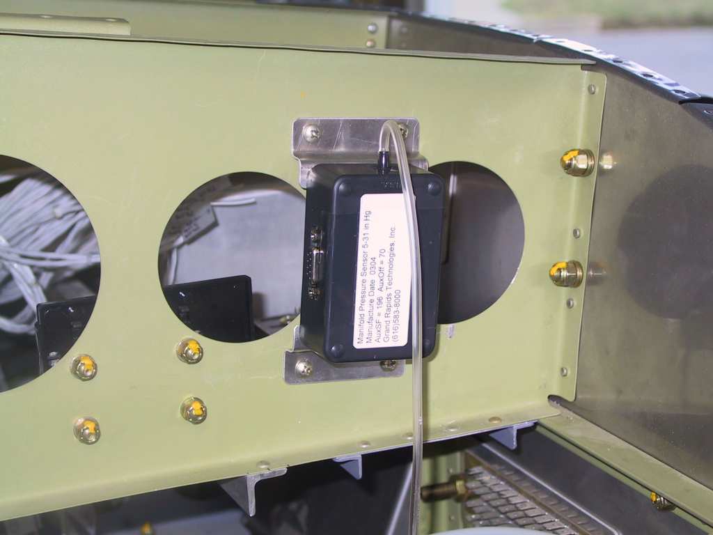
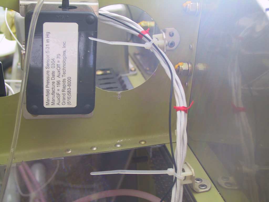
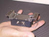
Me and pops made some Z brackets to mount the GRT manifold
pressure sensor. Some folks have just velco'd this in place. I
wanted something more sturdy. And here's where we mounted it, on the
F-745-R.
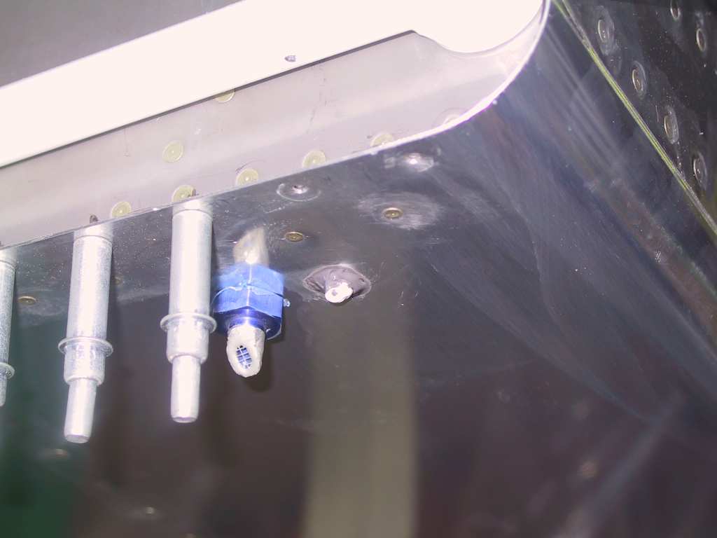
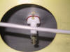
GRT OAT sensor is not located just outboard of the left side fuel vent
pickup. I unibit the hole until it was a snug fit and then buttered
it into place with proseal. No pictures but I also prosealed the
firewall recess. I just stuck a good gob of the stuff into the holes
and cracks. Also buttered up the bottom skin where it meets the gear
weldments.
  |
| 8/27/04 |
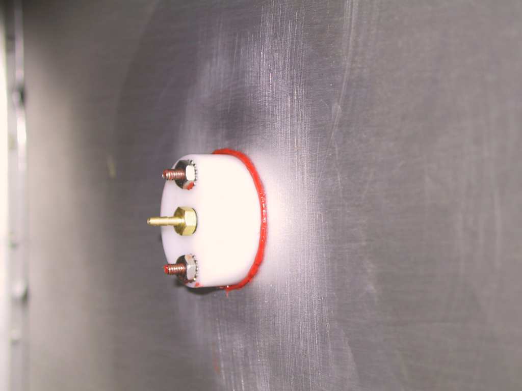
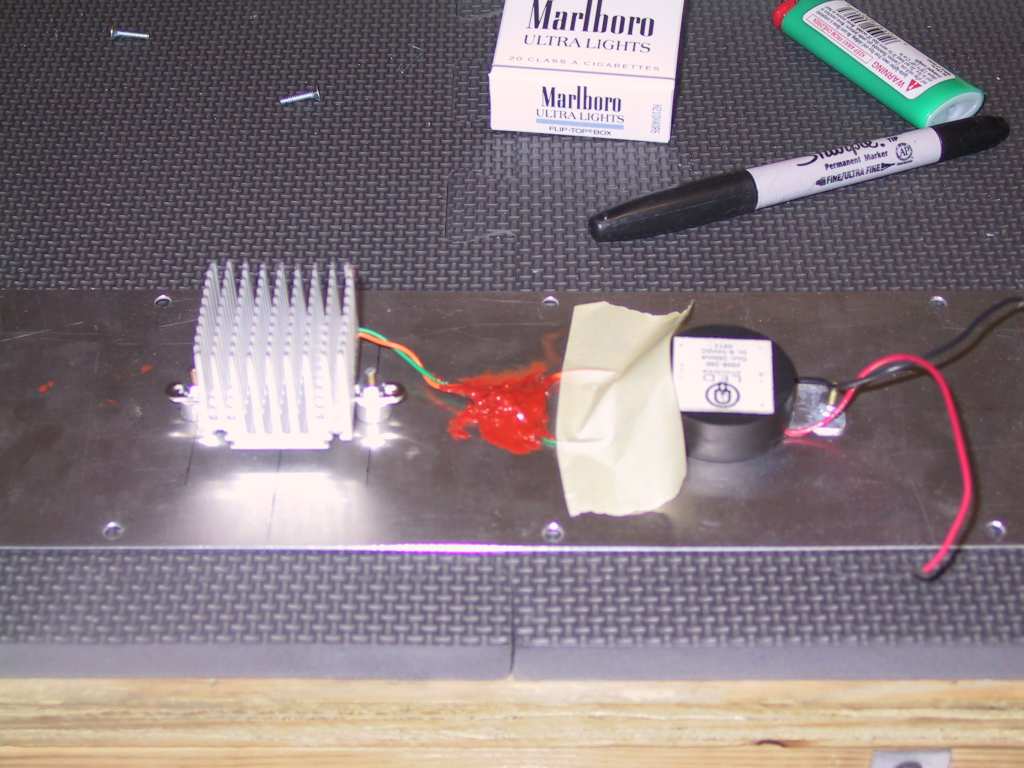
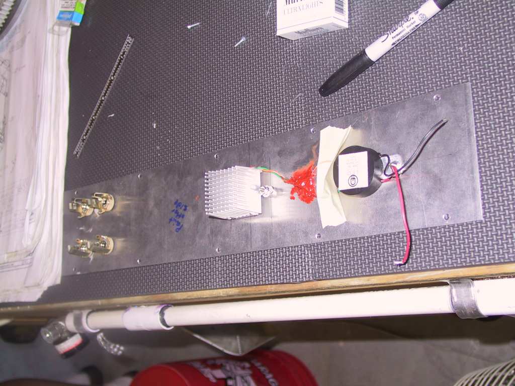
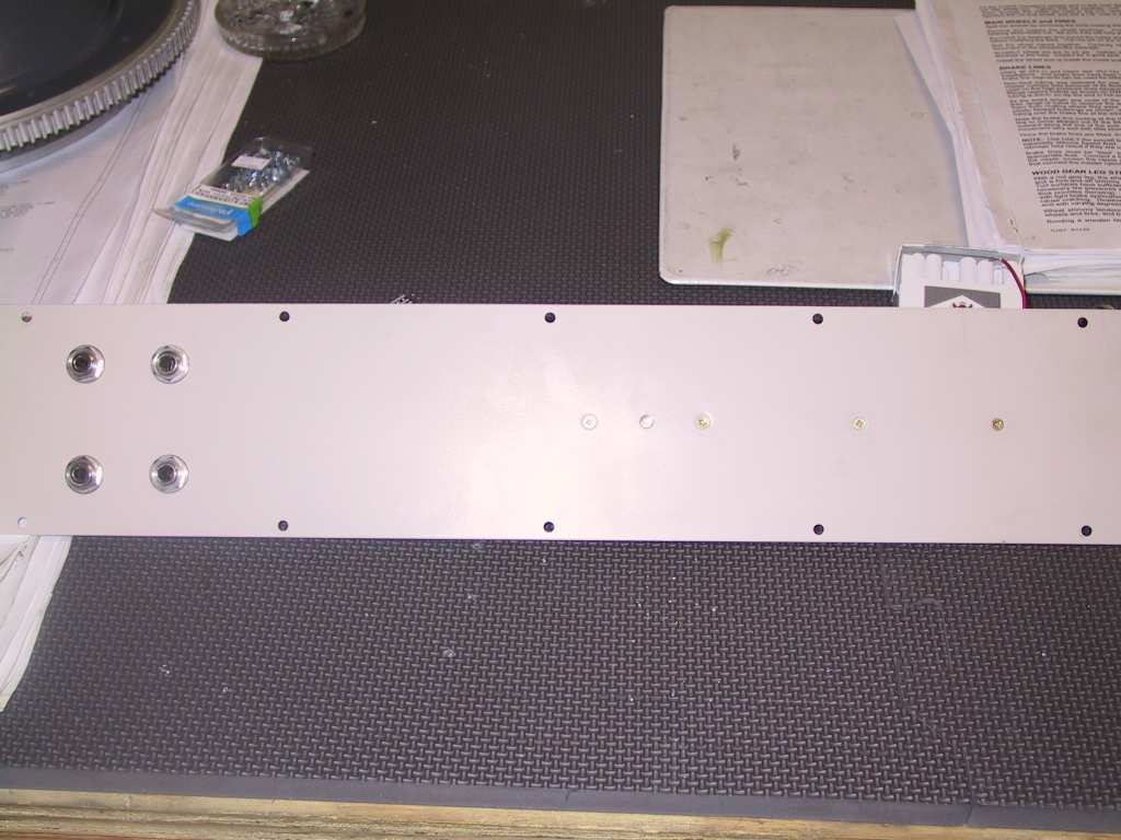
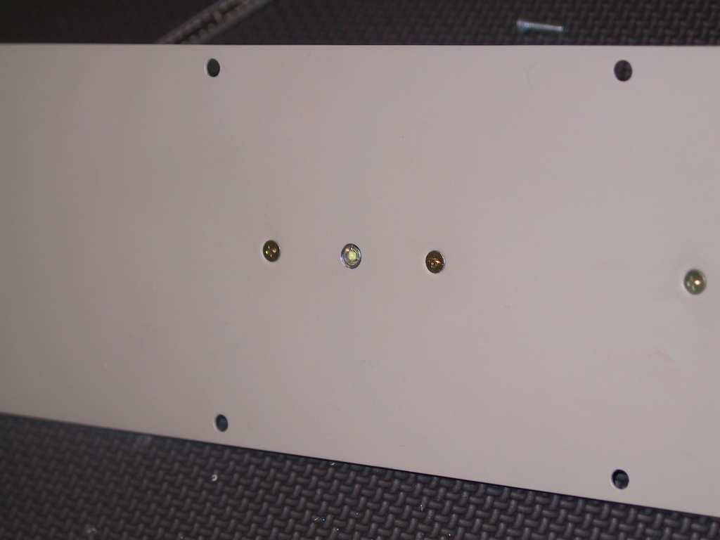
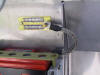
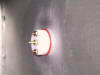
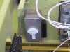
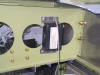
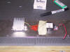
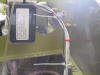
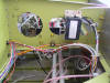
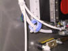
Some more piddly stuff tonight. I mounted my Luxeon
Star led on the back of the cover plate which also houses my pilot/copilot
jacks. This is sooooo cool. All you see is the very tip of the
LED and this sucker is bright! Mounted the power puck next to it and
RTV'd all the wires in place. The tape is just holding the wire
down. I love innovation.
    |
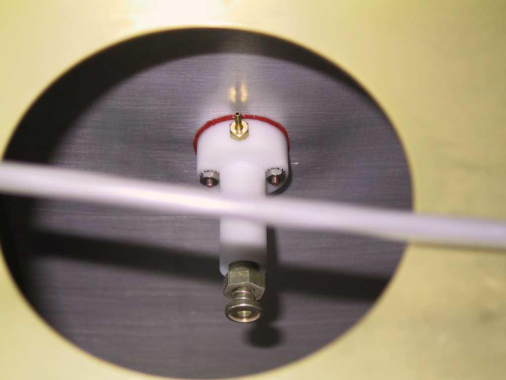
| 9/5/04 |
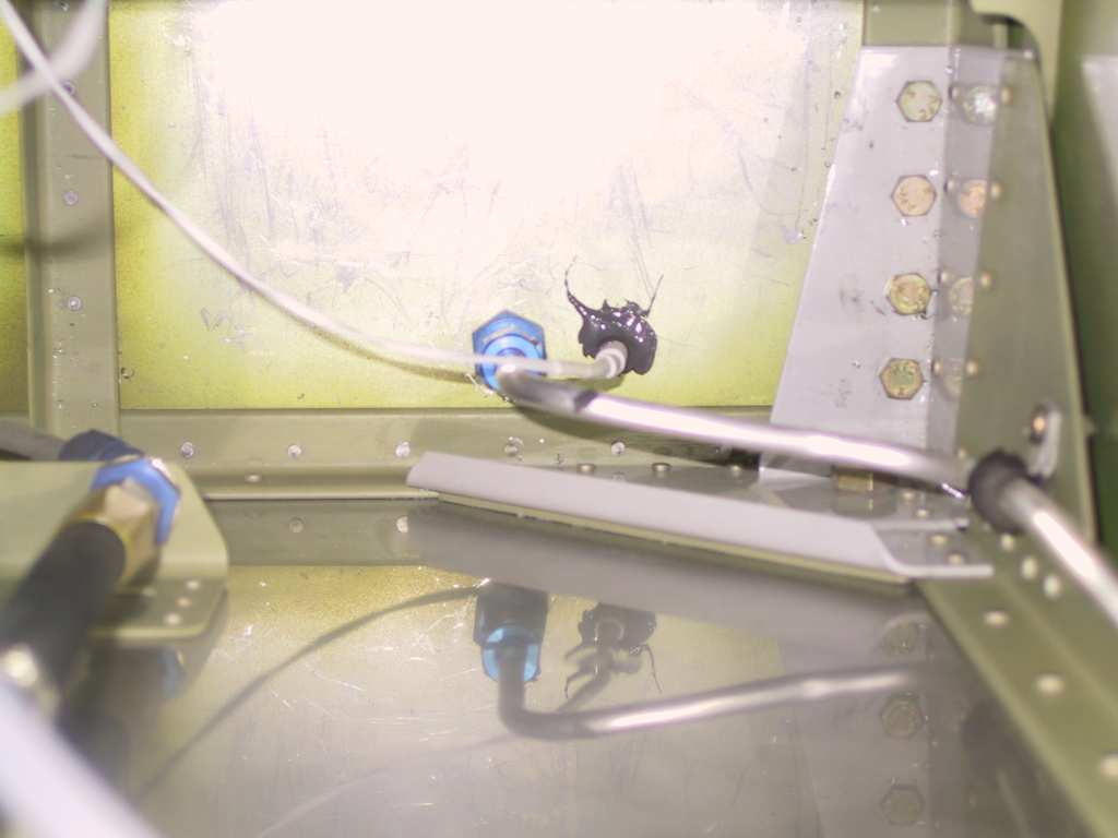
Ran the AOA static wire to the AOA "brain
box" with a T
nipple which was provided.
 |
| 9/6/04 |
I've got wires coming out of my a** now. Jeese, will
it ever end?
    |
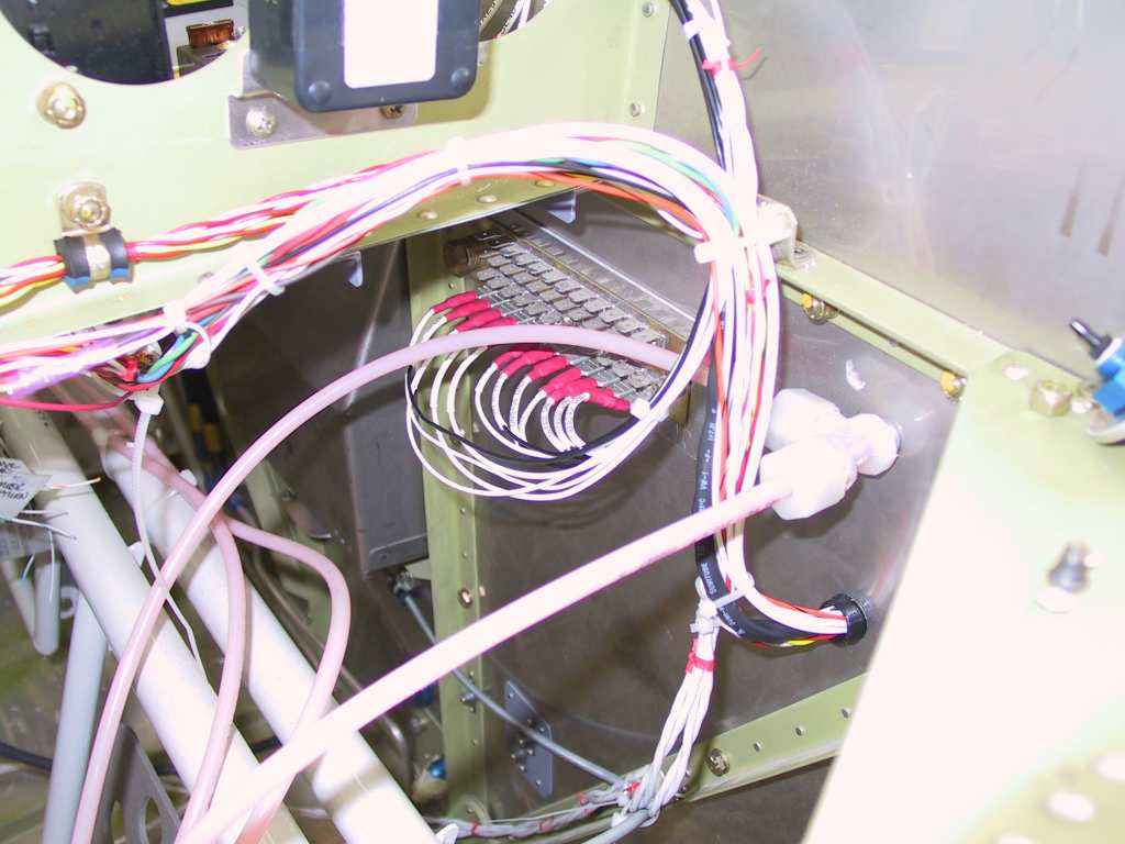
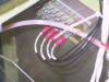
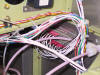
| 9/12/04 |
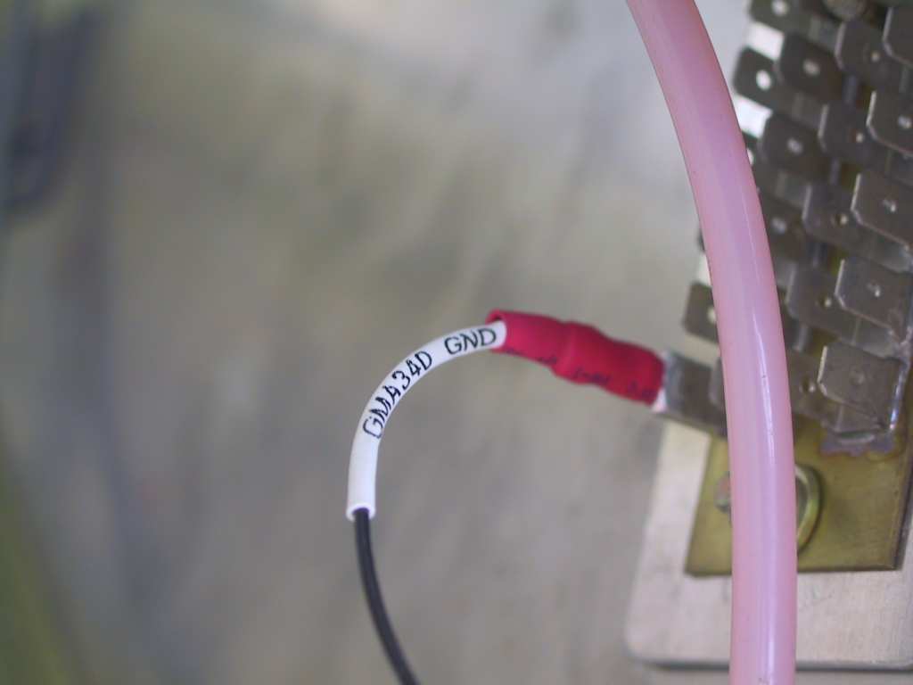
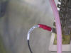
I tie-wrapped the pilot and copilot wires to make them
more manageable. David Richardson picked up some of this red wrap
from Max Industries in Gardena. I have both blue and red.
Combine that with the white cables and you have a very nice flag colored
wiring. Kewl.
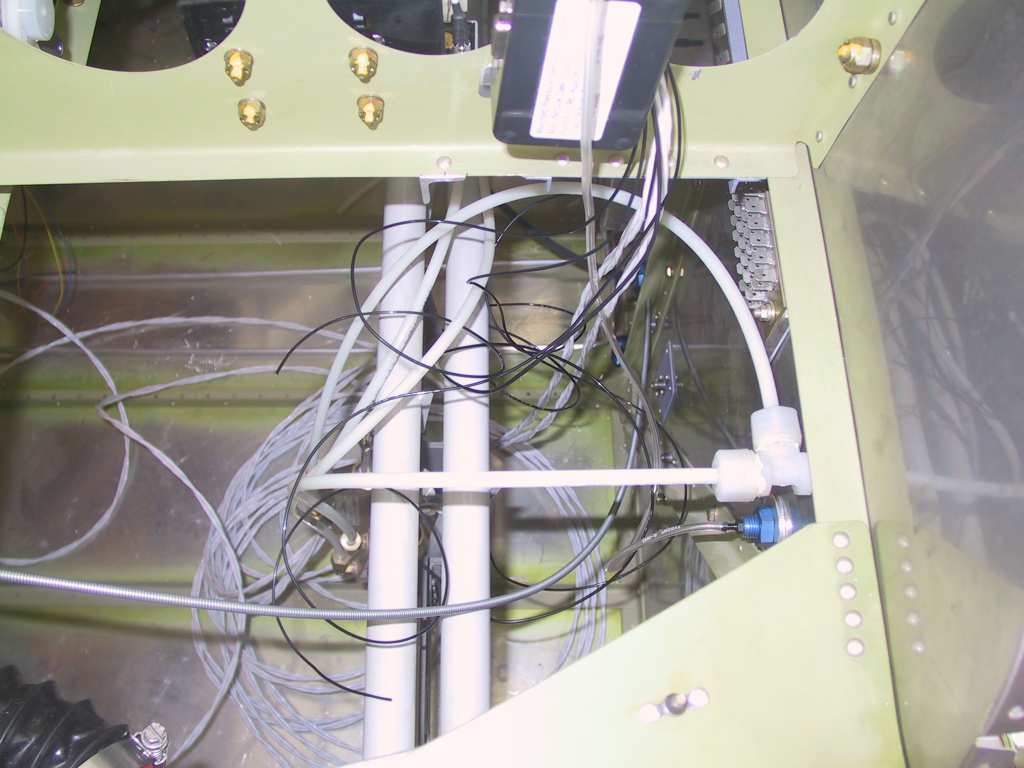
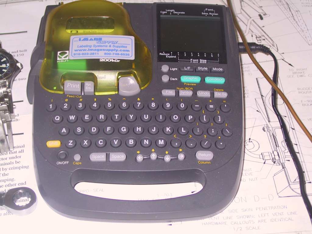
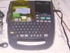
More wiring runs and the first of the ground connections. I
picked up an awesome wire label machine a while ago. It's a K-Sun
2001 XLST which I purchased from
Image Supply for around $300 bucks, I don't remember exactly now.
This thing is a work of beauty. You really should check this out if
you want a machine printing your shrink-wrap labels instead of the old
fashioned "by-hand" method. I would list all of it's features but
just do the homework for yourself and make the determination if the cost
is justified. For me it is because I label everything and every
wire.
     |
| 9/16/04 |
Running wires, no pics. |
| 9/17/04 |
Running wires, no pics because this is really really boring. |
| 9/18/04 |
Finally a break. Went fishing. |
| 9/19/04 |
Running wires, again. No pics. I'll have some
when I figure this out. If I don't kill somebody first. |
|
10/3/04 |
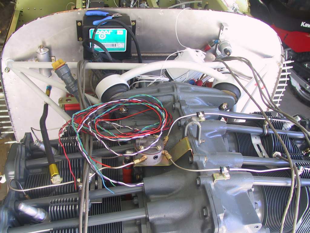
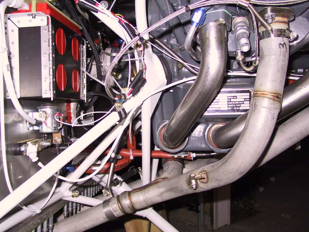
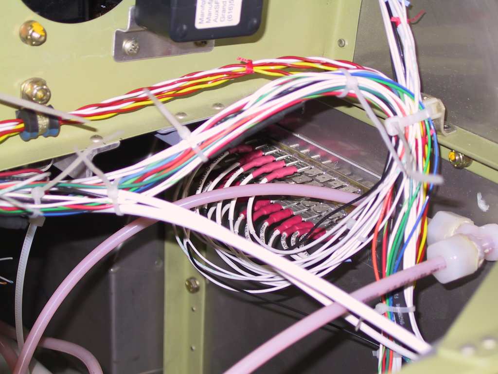
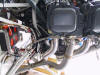
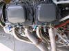
Worked on wiring all weekend and made substantial
progress. On Friday Dave Bristol came by for another inspection.
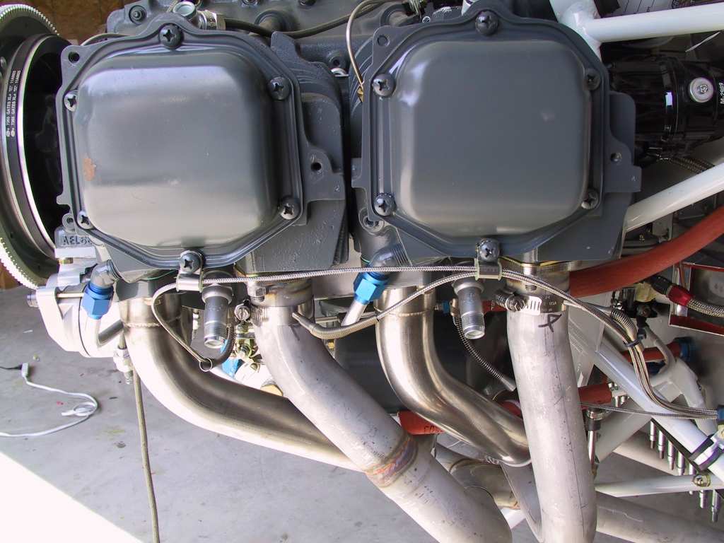
He gave some great answers to my questions. Firstly I was concerned
about where and how to run the CHT and EGT wires back to the EIS.
It's pretty straight forward but I'm trying to eliminate using plastic
wire-ties in the engine compartment. I won't be able to completely
eliminate them but I did buy some high temperature wire ties from
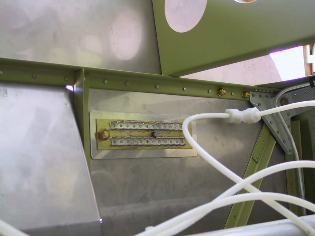
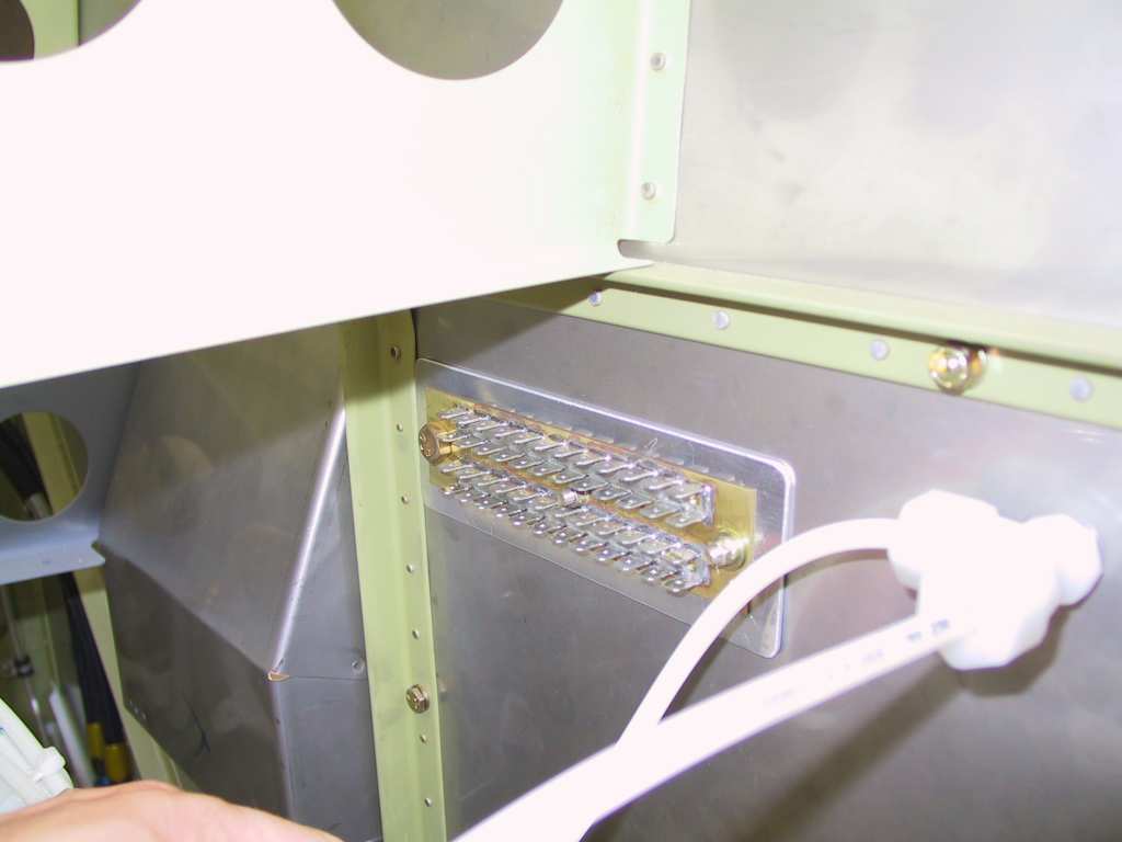
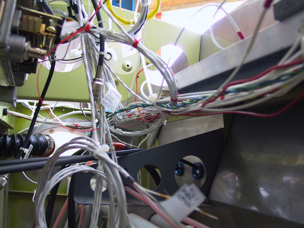
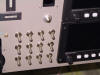
Steinair. Here are some shots of the wire runs. I have to
firewall pass-through, one on each side of the firewall. I also
have the two-part stainless covers and I'll fill the area with firewall
sealant when all is done. None of the connectors are heat shrunk yet
until I test the connectivity of all EGT and CHT probes.
Next I had to fabricate a longer plate which the control cables are
routed to under the sub panel. My panel is about 2 inches deeper than
the standard panel and the cables were going from the panel up to the
sub panel then downwards. The mixture cable was a bit short so
extending this part make it fit perfect.
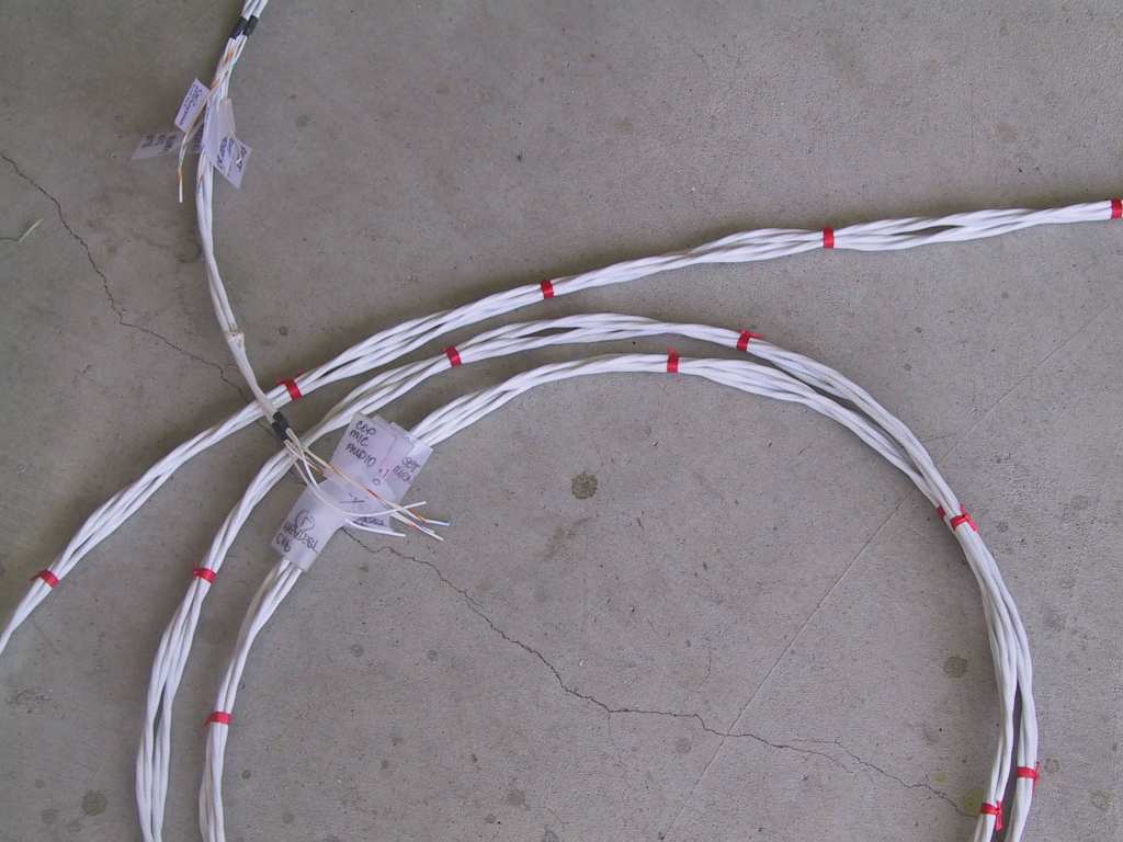
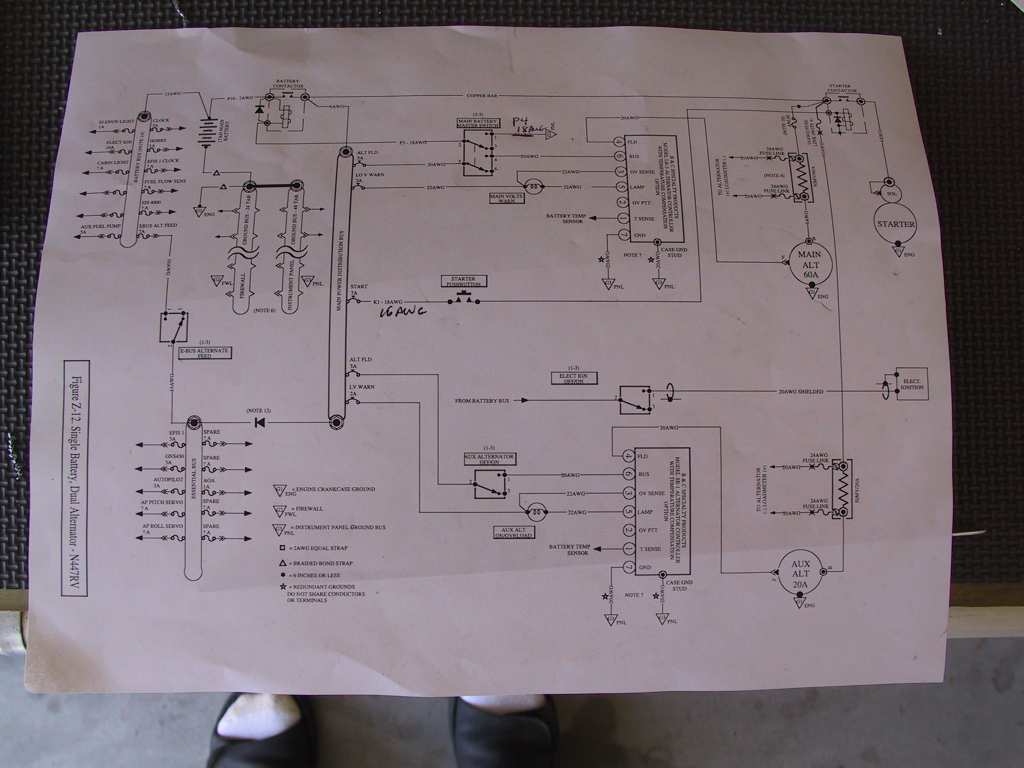
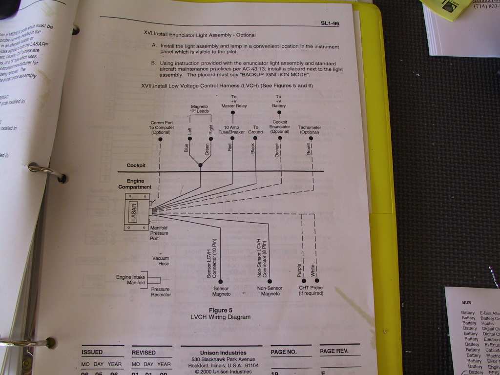
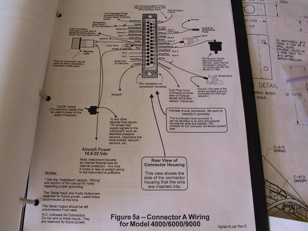
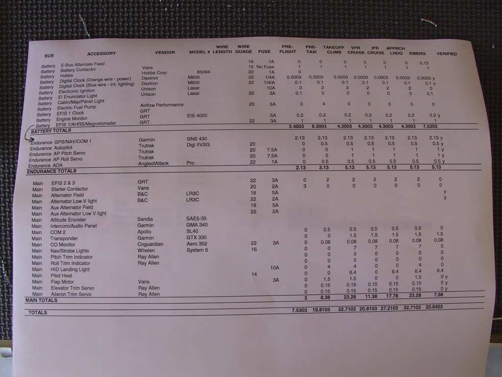
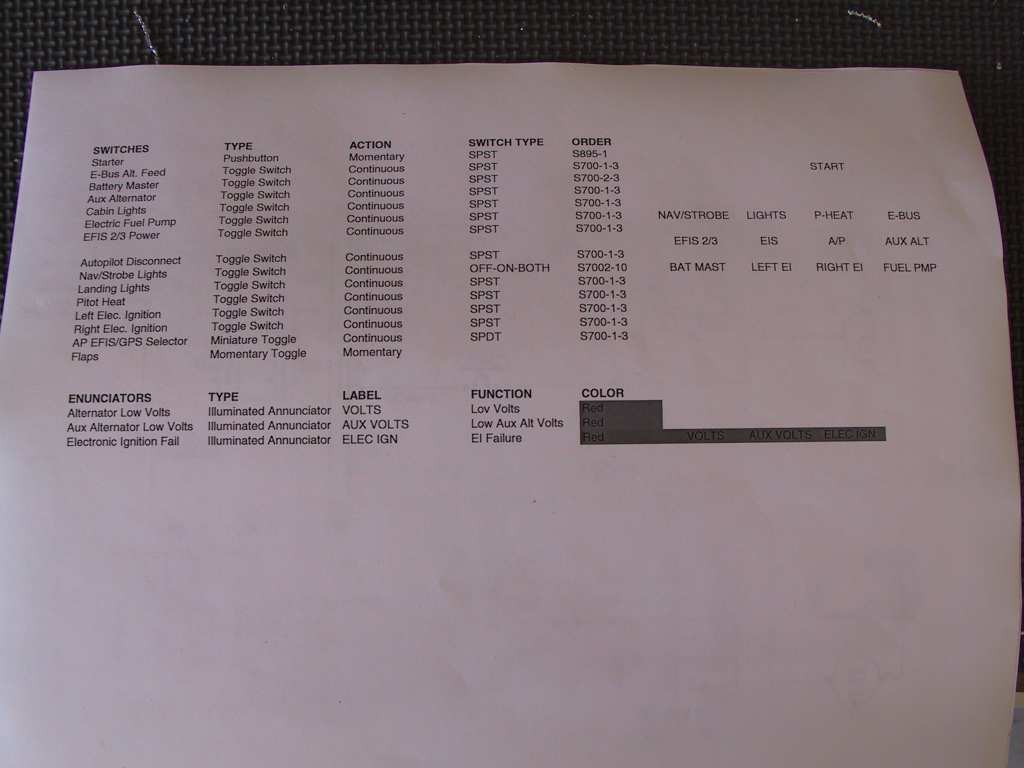
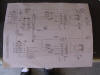
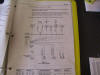
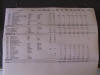
First thing you do is read, read, read. Then calculate,
calculate, calculate then start running wires, one at a time, labeling
each appropriately. It all looks very confusing but you get the hang
of it after a few weeks. Once these bundles are wrapped properly it
will look like art. Here are some of the documents I was messing
with today.
    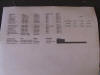
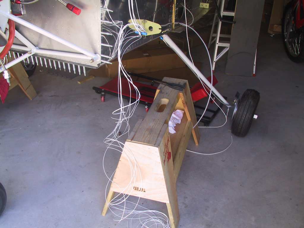
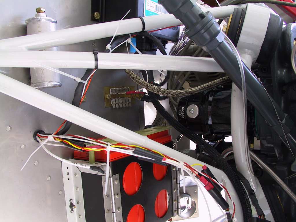
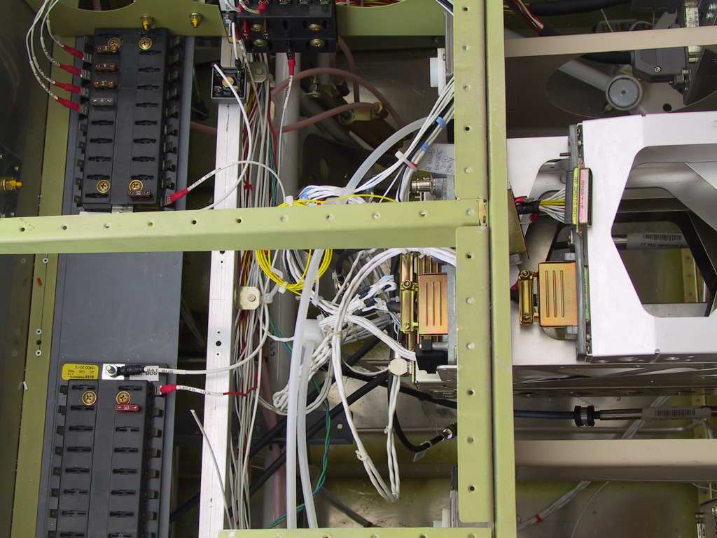
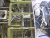
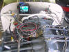
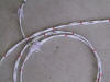
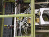
And here are some of the results. Not done yet by any stretch of
the imagination. Maybe these pictures will help, probably not since
each of us is going to do this quite differently depending upon what you
have in your bird and the electrical system you design.
   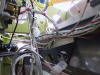
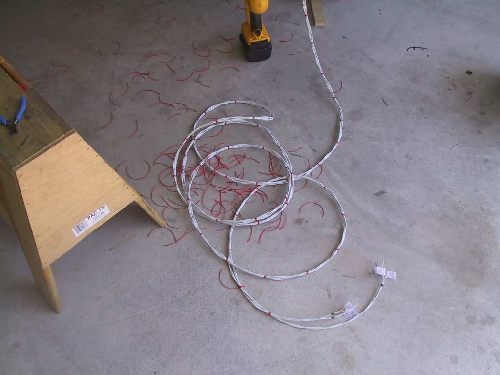
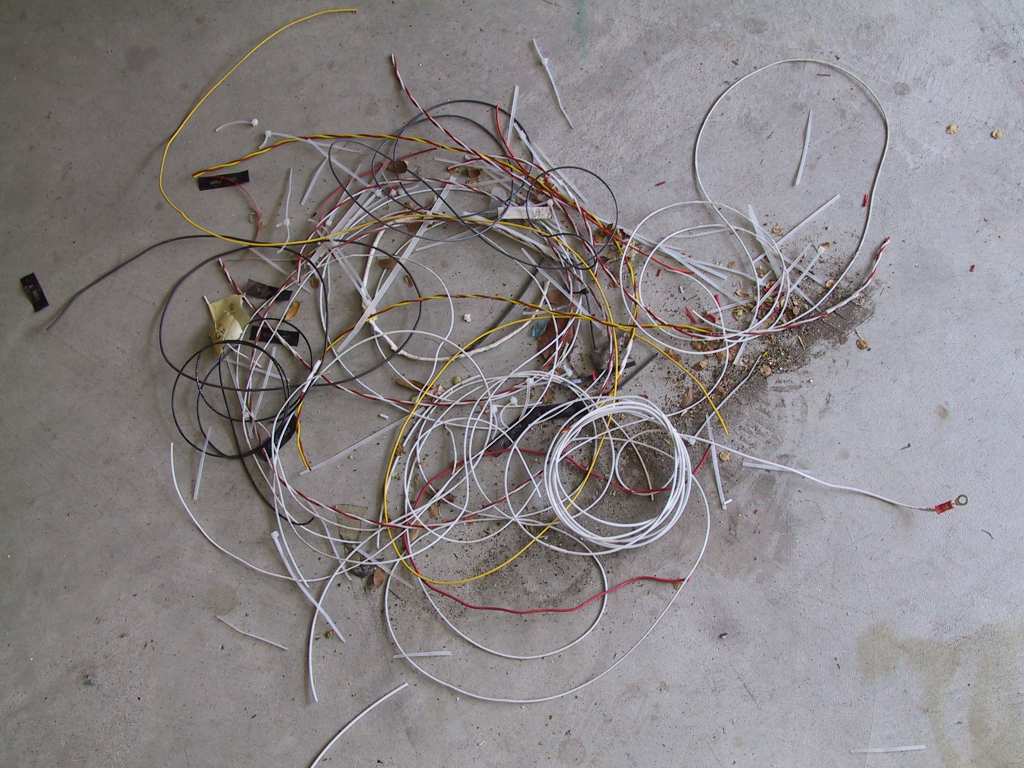
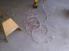
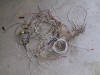
Here's what's left on the floor. Looks like a wire barbershop.
Wanted to mount my Hobbs pressure transducer but the only spot I have
left on the manifold interferes with the firewall. I'm going to make
either an aluminum or UHMW standoff for the manifold. Pictures at
11:00. |
|
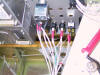
10/5/04 |
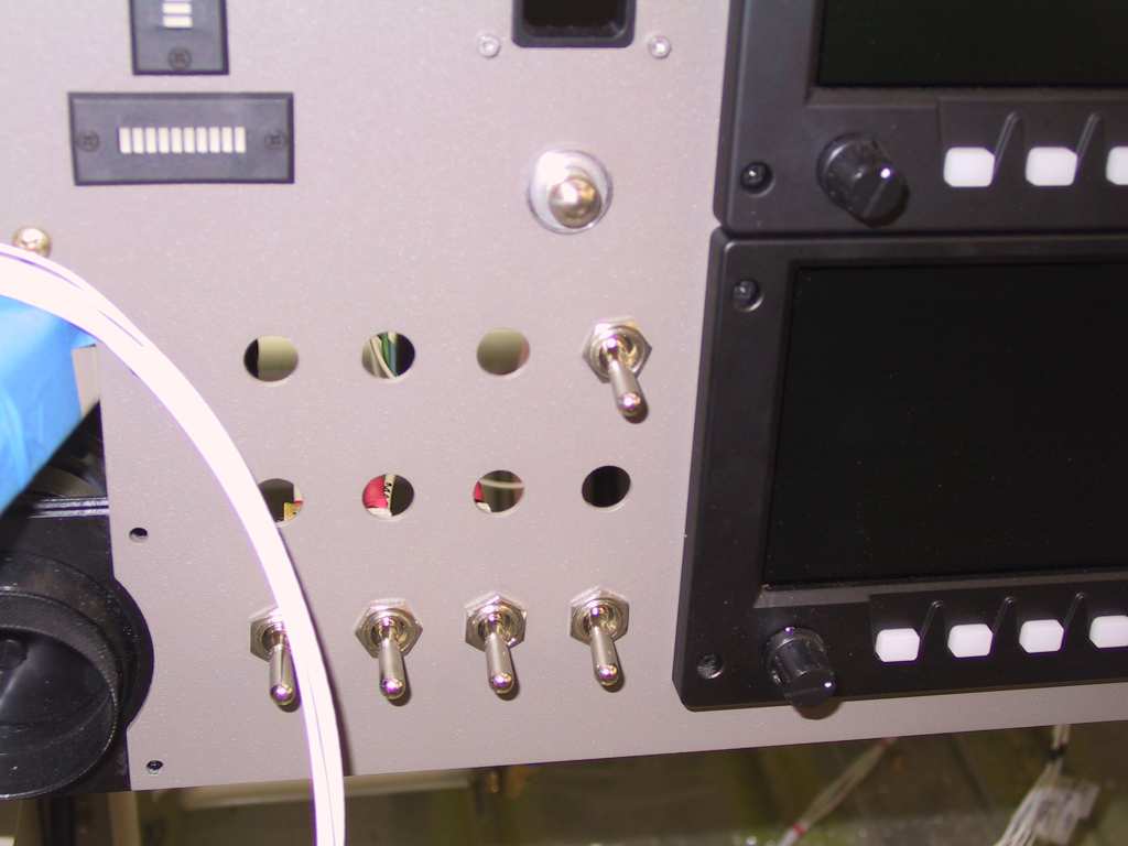
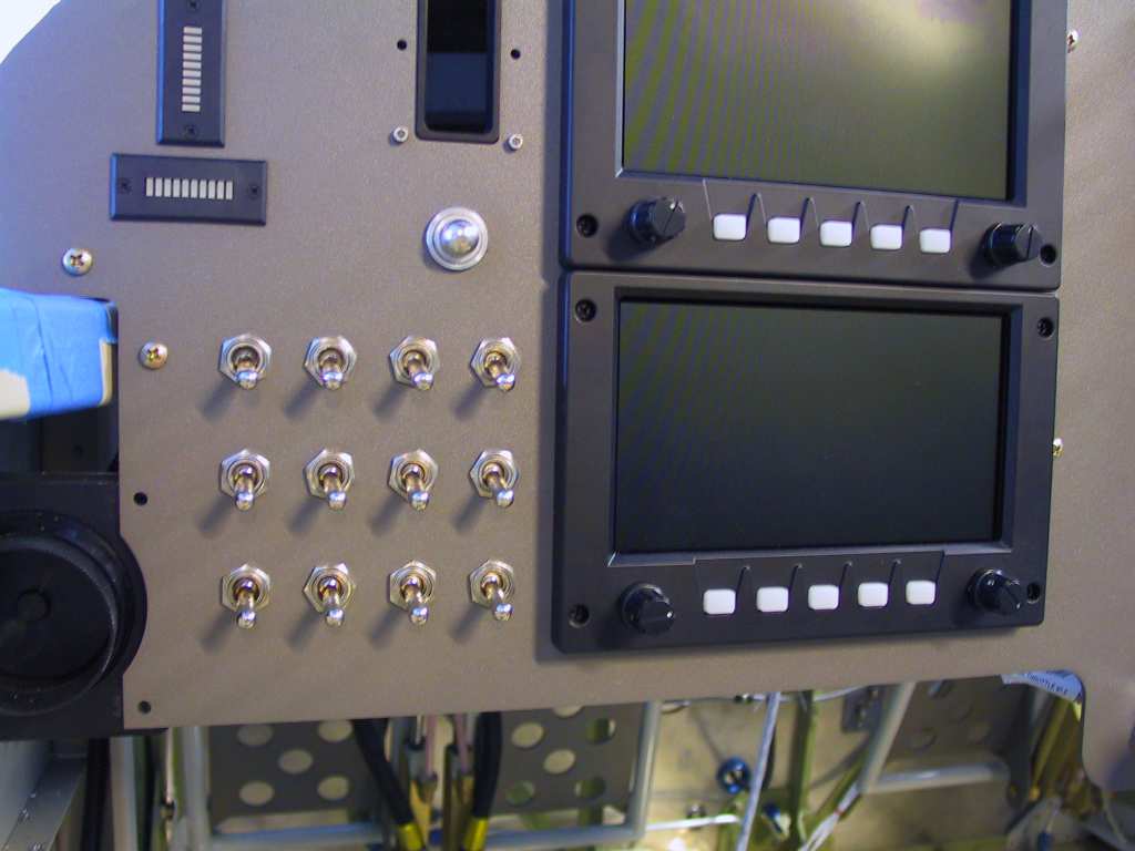
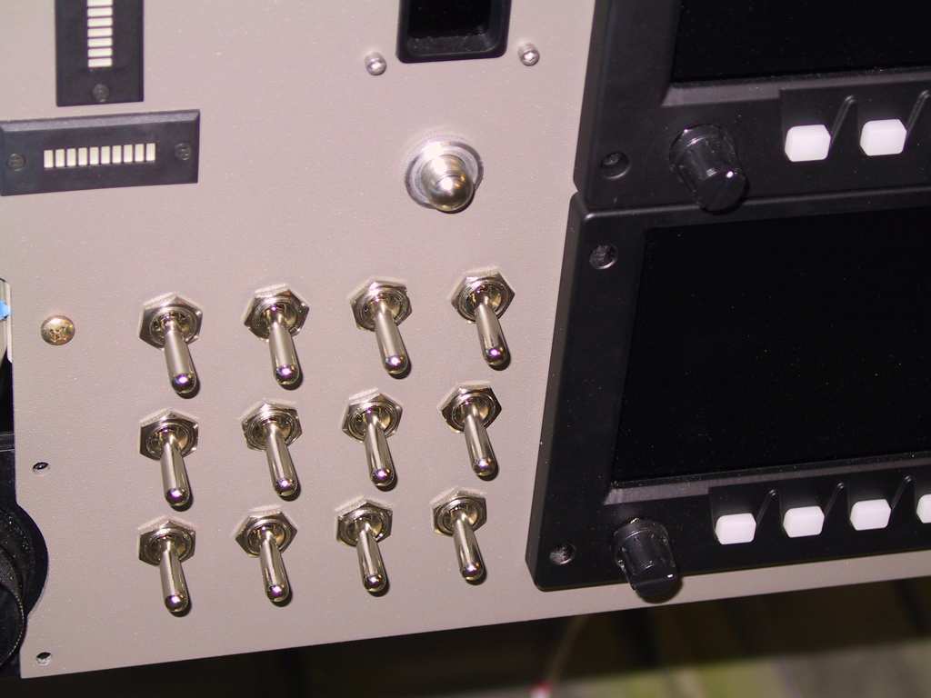
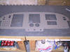
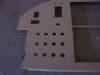
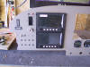
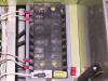
More wiring and all the switches are installed. This
isn't permanent yet because I have to figure out how I want to label the
switches. With the rough surface of the powder coated panel I can't
stick on labels. I'll have to make a label backing plate.
  |
|
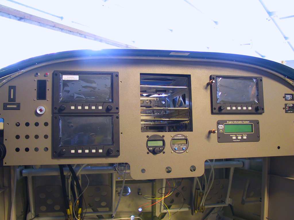
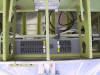
10/6/04 |
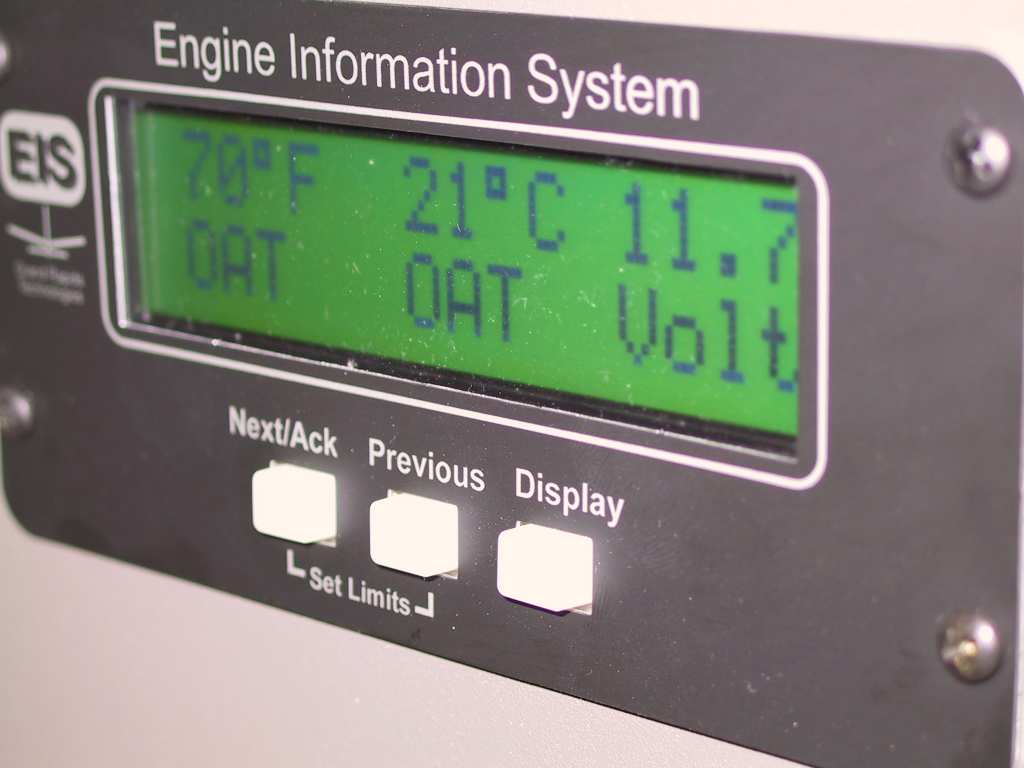
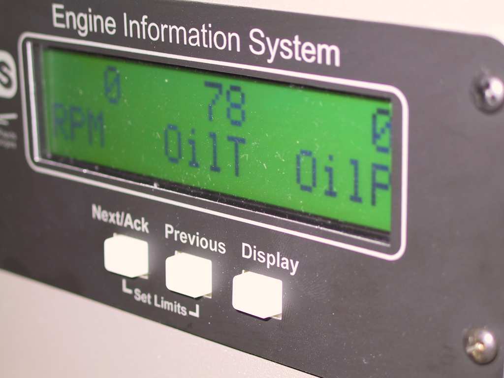
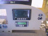
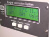
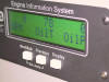
Got the EIS powered up on the E-bus and wanted to verify
that the CHT and EGT probes were connected and working properly.
Yep, no problemo.
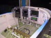
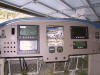
Next all the final power runs were made for the instrument panel items.
It sure was nice to see all these lit up. Look, can you see the
light at the end of the tunnel???
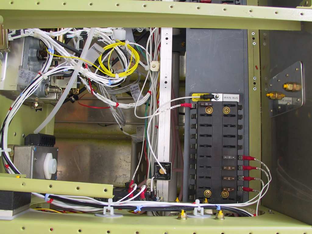
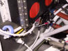
Ran the wires for the B&C 60A alternator and the power feed for the
main bus. It gets it's own firewall pass-through. It's the
smaller of the wires in the leftmost pass-through of the last picture.
   |
|
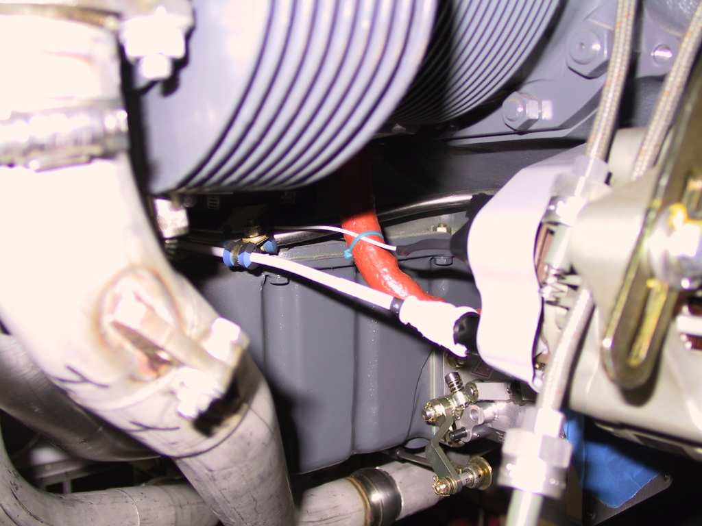
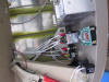
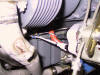
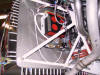
10/7/04 |
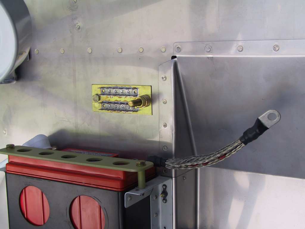
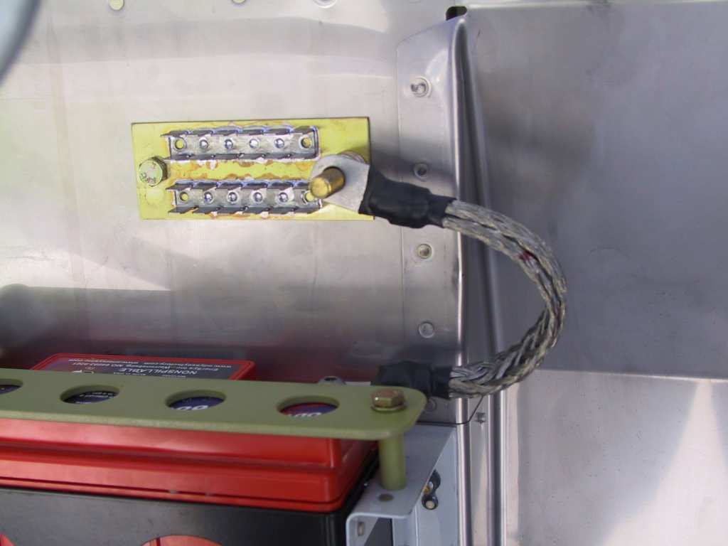
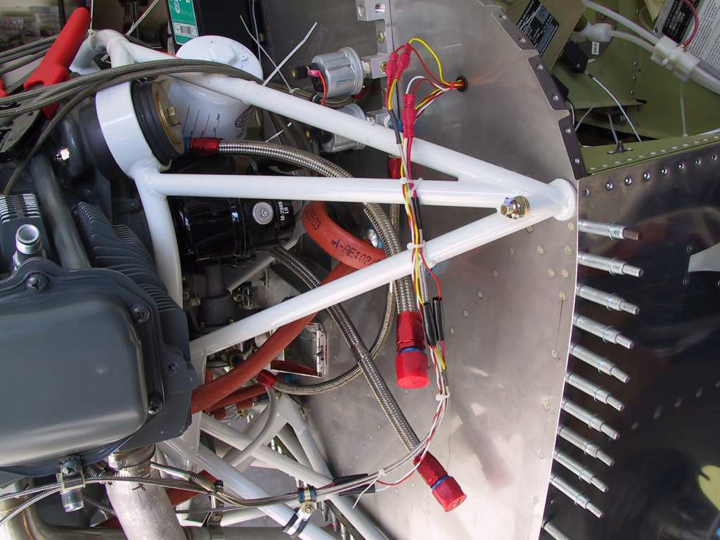
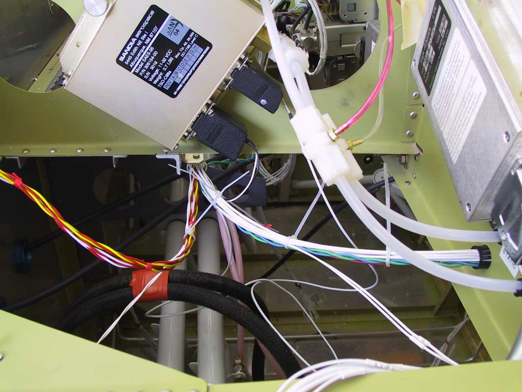
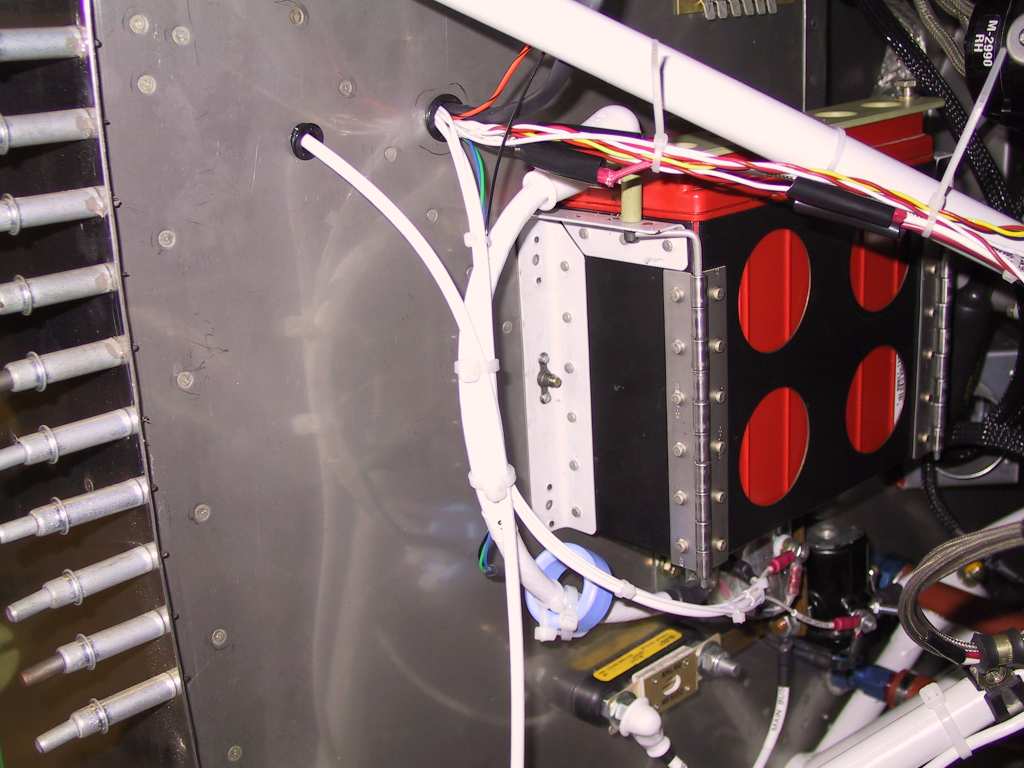
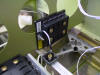
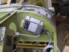
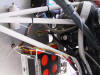
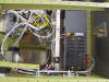
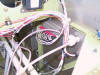
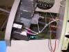
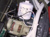
Here's where I installed the Hall effect sensor which
connects to the EIS 4000. I couldn't find a suitable mount for this
so I used two giant wire ties which are cris-crossed around the battery
positive lead. This is the only lead from the positive side of the
battery so I know that there will be no other current leaks and the sensor
will be reading exactly what is coming in or going out of the battery.
It's not going anywhere.
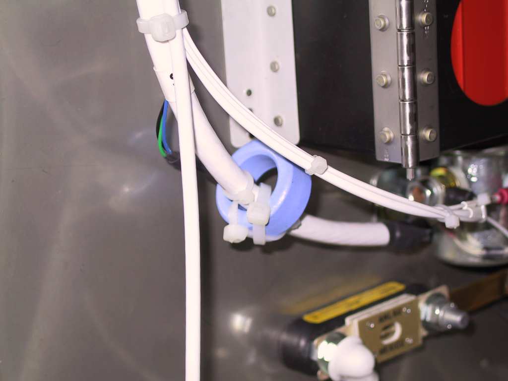
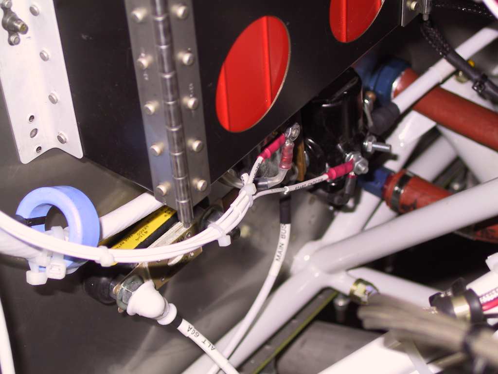
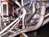
Here you can see the battery contactor and starter contactor wires as
well as the blue donut.
 |
|
10/8/04 |
Paperwork today, boring, no pictures. |
|
10/9/04 |
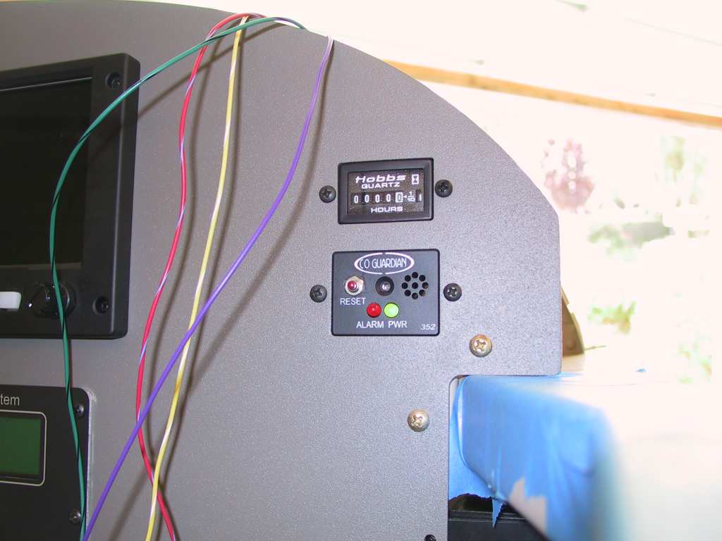
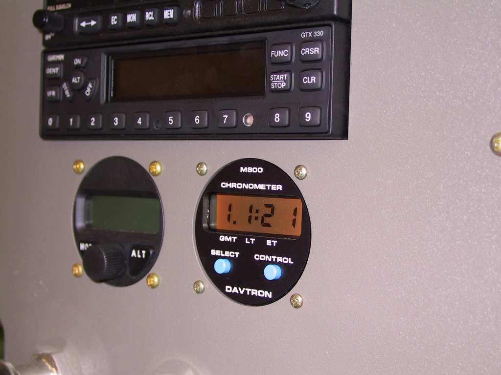
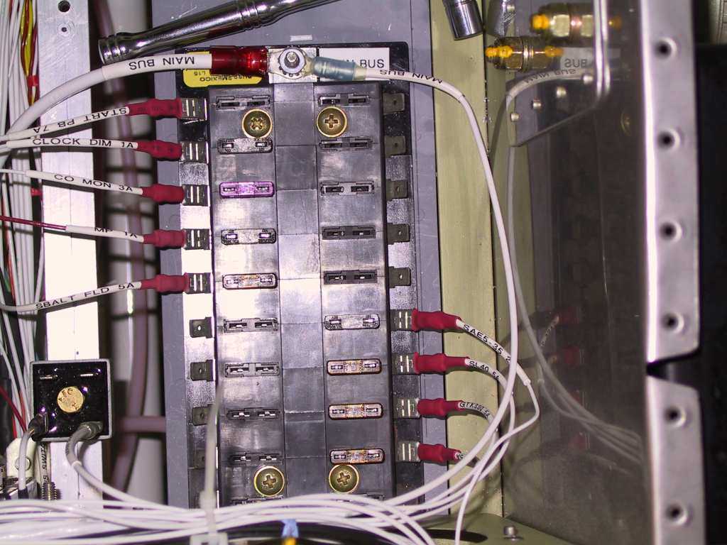
More things are getting power. CO monitor has power.
Davtron clock get power. I decided against a dimmer. I can
add it later if needed but the clock gets power from the battery bus to
maintain time and gets backlight power from the main bus when powered up.
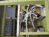
The ground tab is getting fuller. One thing to note here is that
you should get the biggest ground tab you can, get the 48 point ground
tab. Trust me, if you have fat fingers like me you are NOT going to
be able to use every row. There just isn't enough room to get your
fingers in there to shove the spade on. I use alternating rows to
enable my fingers to get a hold of the spade and shove it on. Now if
you have a vacuum system... shame on you.
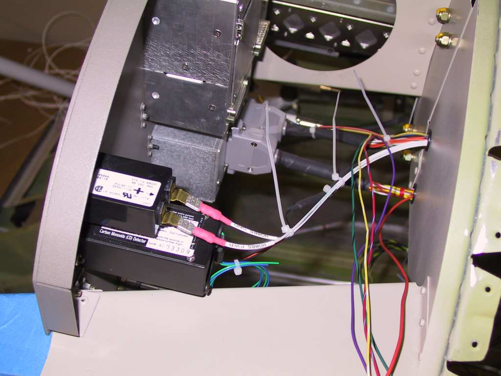
Hobbs meter wired to the hobbs pressure transducer. I haven't
figured out how I'm going to mount the hobbs pressure transducer.
I've got an idea and I'll show you later.
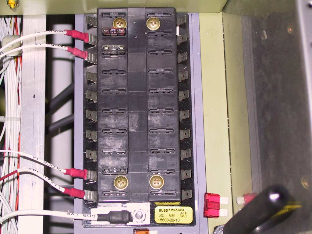
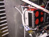
Main bus, battery bus and E-bus getting more stuff.
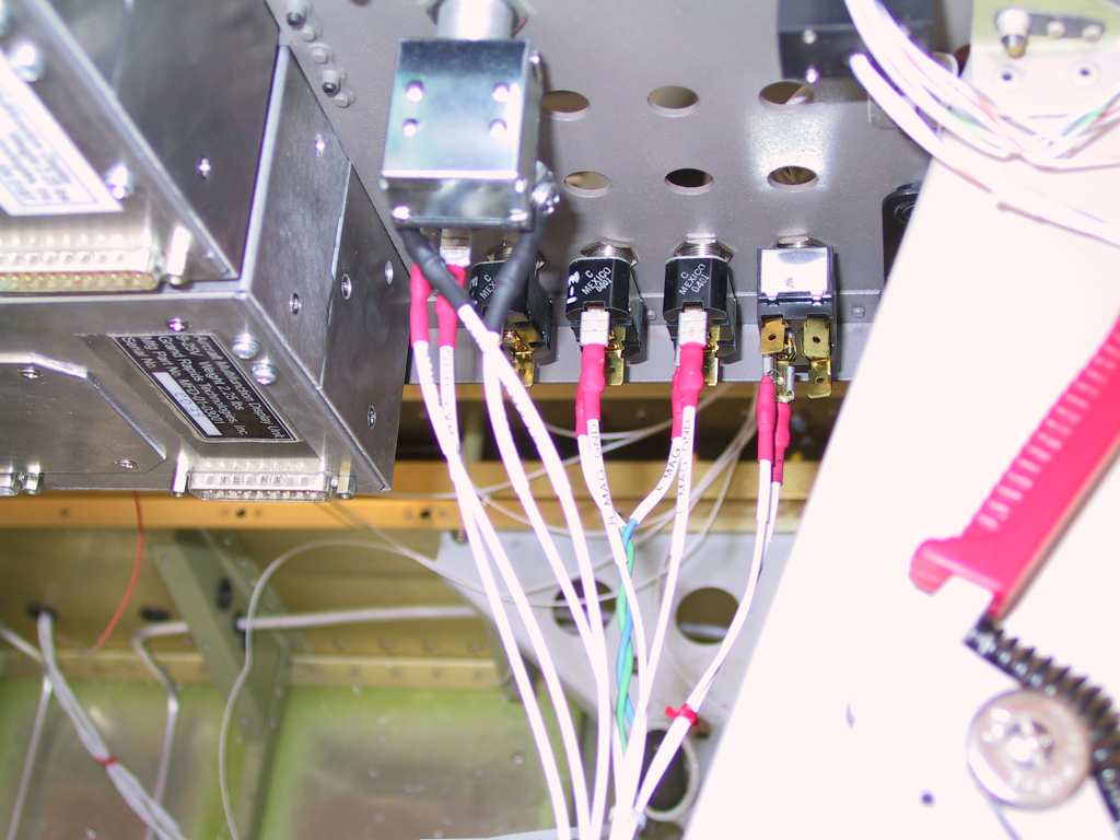
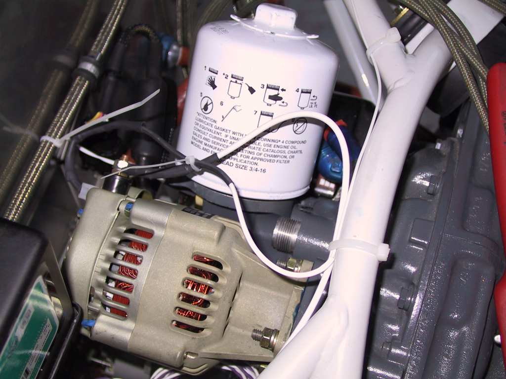
Alternate B&C alternator all wired up. Here you can see the Field
and B wires coming back to the engine mount and then they route along the
right side of the firewall.
 |