| 10/23/04 |
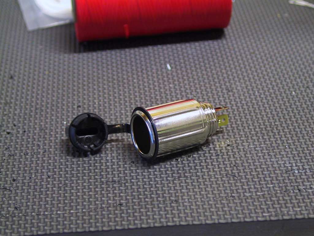
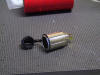
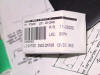
I received this 12 cigarette adaptor today. But I'm
having second thoughts about sticking this ugly thing on the panel.
Hmmm.
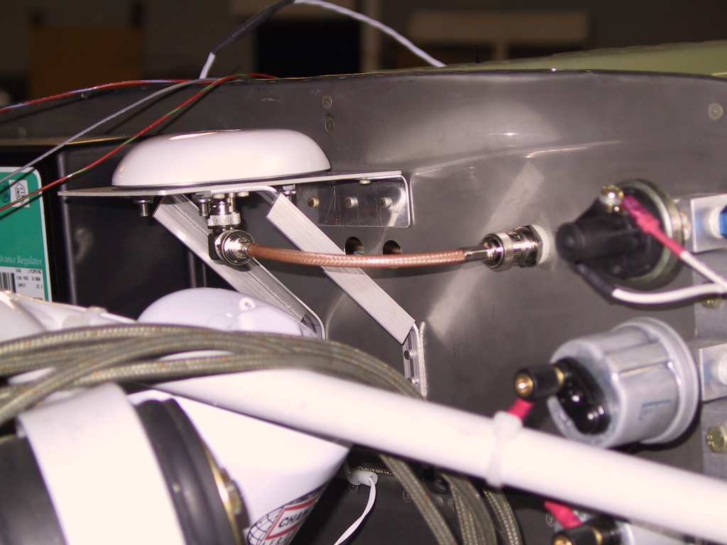
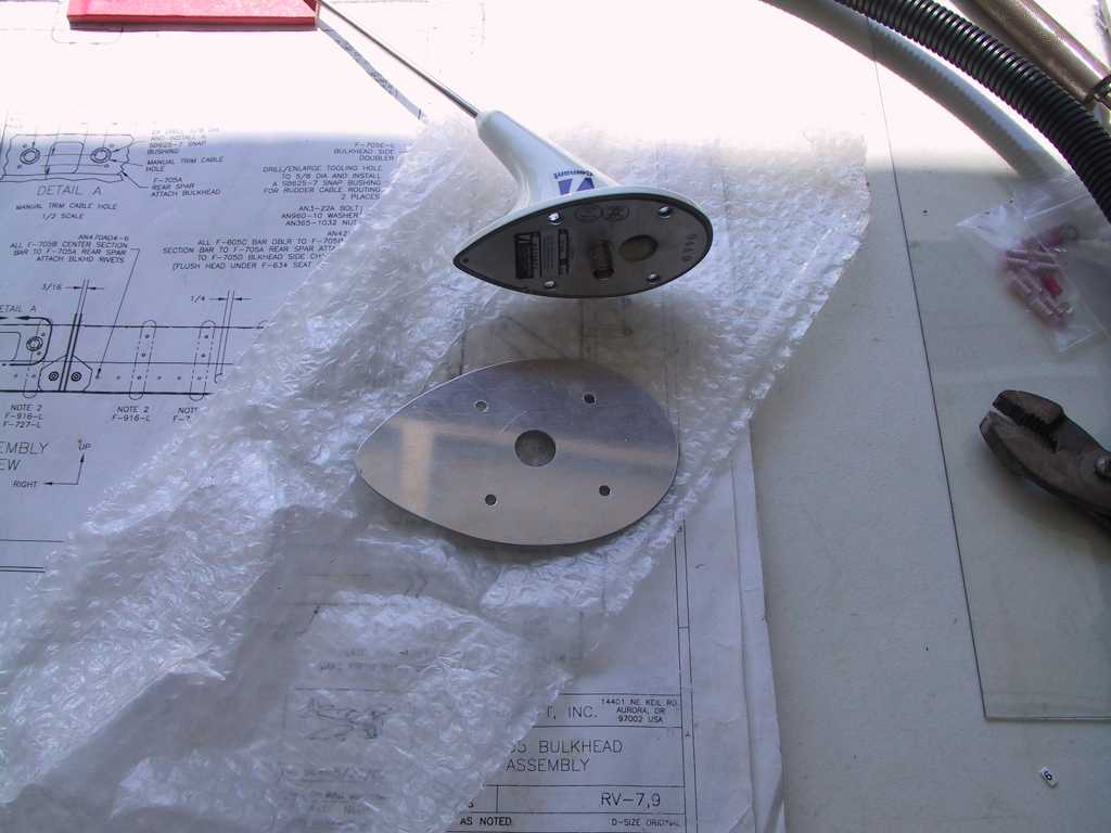
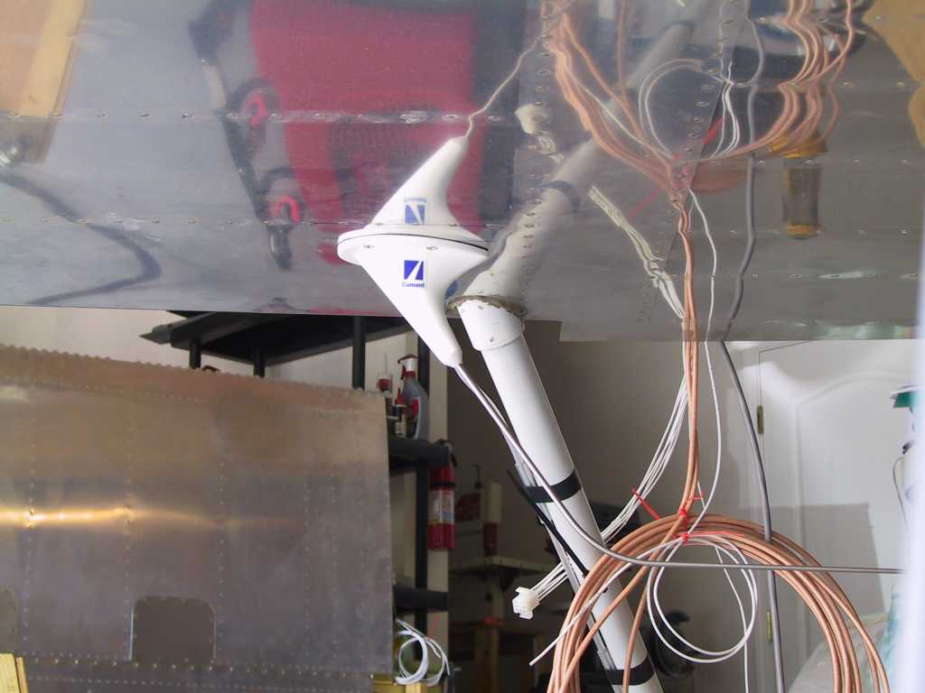
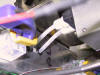
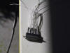
I also wrapped up the cable running from the GPS antenna to the
firewall fitting. I tried two attempts at running the cable under
the flange I made to hold the GPS antenna but neither worked out. On
the first attempt it was impossible to make a cable that small. The
crimp fittings would have to overlap. The second was a bonehead
mistake. So I ordered two 1/2" stainless hole plugs. I'll just
pop them in place with some fire sealant.
 |
|
10/24/04 |
Did a bunch more studying of the wiring for the
EFIS/GPS/AP today. I'm considering all the options. I think
I'll have to break apart the wiring harness that Stark built for me.
Turns out that I need to have the GTX 330 transponder send TIS (traffic)
information to the EFIS in order to display traffic on the displays.
Well since I didn't ask him to leave extra pigtails, he didn't. So I
have to cut and splice. What you need here; ask John Stark (or
whomever is doing your harness) to drop two wires off the GTX330 P3271
connector, pin 30 (ARINC 429 A) and pin 28 (ARINC 429 B). Both of
these are traffic data which you will connect to the GRT ARINC 429
interface, either C-1, C-2 or C-3, C-4 respectively.
You also need to
provide the EFIS with GPS data. That means you need to tap the lines
on the GNS430 connector J4006 pin 24 (ARINC 429 A - VOR/ILS Data) and pin
23 (ARINC 429 B VOR/ILS Data). Those go to the GRT ARINC 429
Interface into pins C1,C2 or C3,C4.
Pins C5 and C9 of the GRT ARINC 429 Interface go to both the Trutrak AP
and back to the GPS 430.
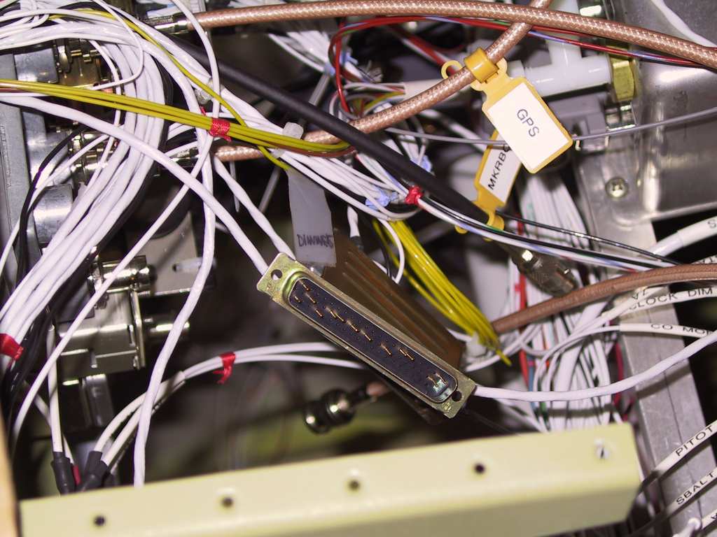
What I think I'm going to do is wire all of these to a DB25 connector
so it's easy to tap into the lines since many of them are shared.
FWIW, I learned that you can tap as many as 5 ARINC 429 devices on one
line (well actually it takes two lines for ARINC 429, both the A and B
lines).
So if someone is doing your harness and you have the GRT EFIS, the GNS
430 and a GTX 330, please ask them to do this, I wish I would have.
Now I have a ton of tedious work to do. Fortunately I haven't closed
up the access yet. |
| 10/25/04 |
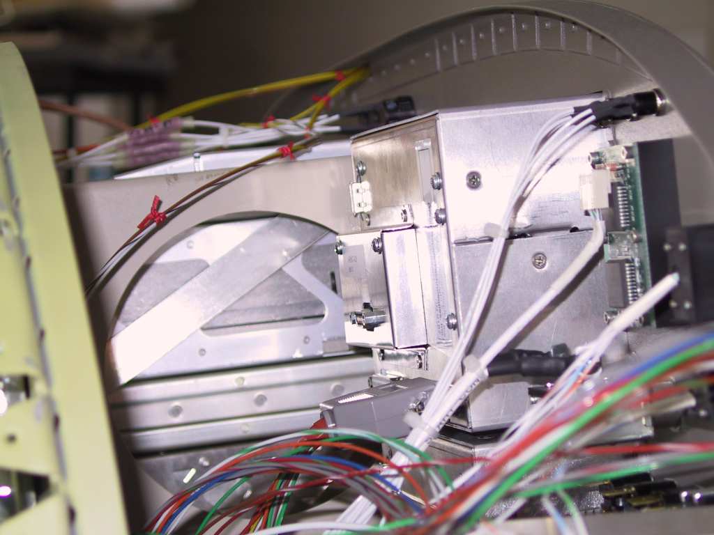
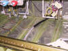
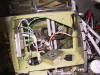
Today I installed the GRT ARINC 429 interface. Wow,
it took almost 2 minutes to do it. The modular approach that GRT
takes is fantastic. See the little 1/2" bulge on the back of the
EFIS unit? That's the interface. Easy like pie.
 |
| 10/26/04 |
Not feeling too hot today. Just studying wiring
diagrams. |
| 10/27/04 |
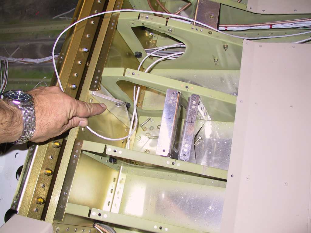
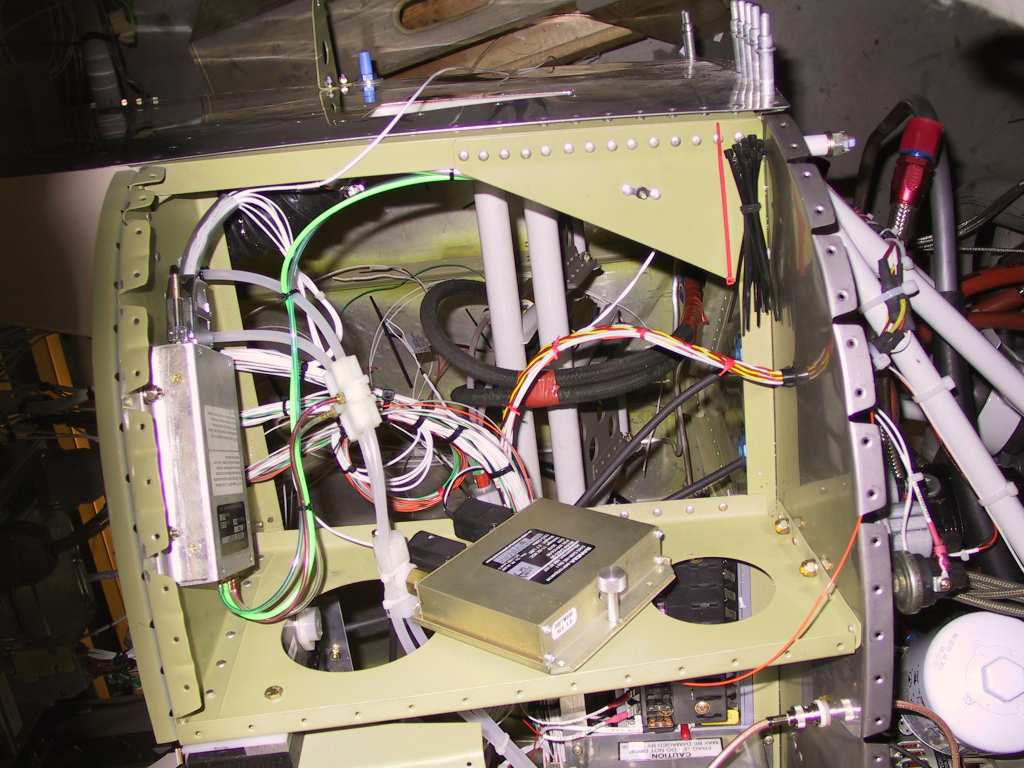
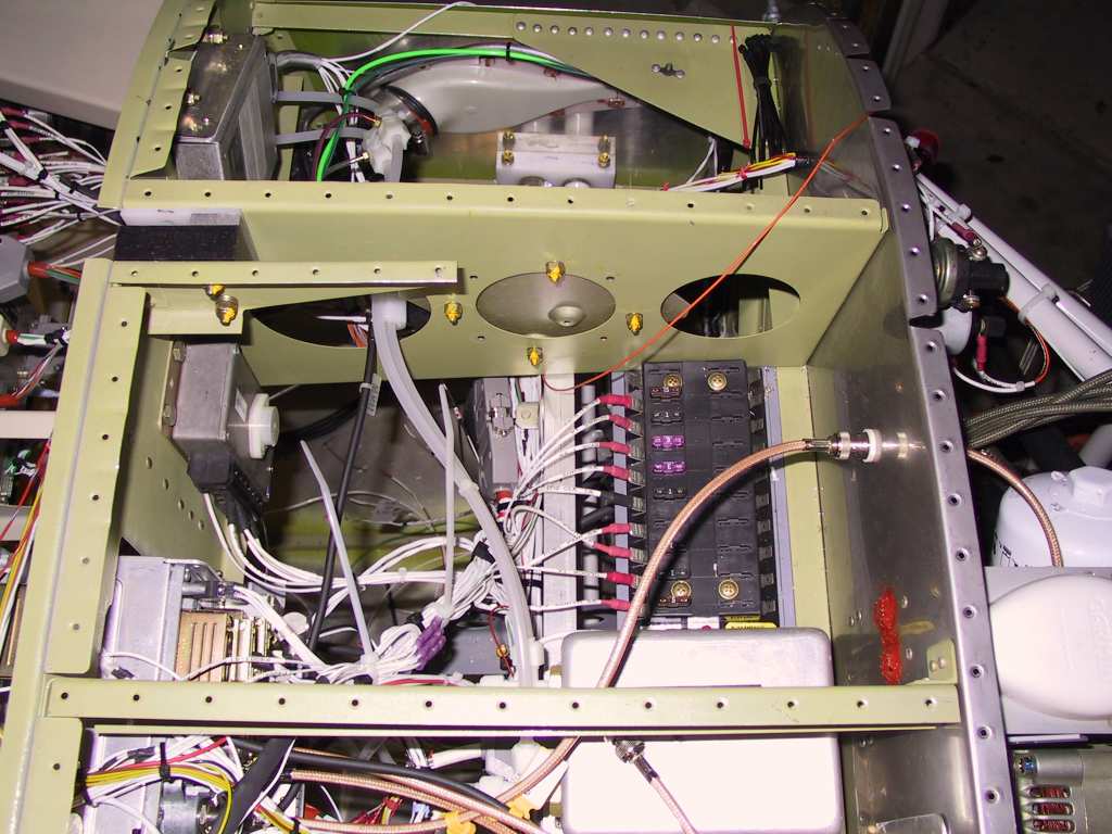
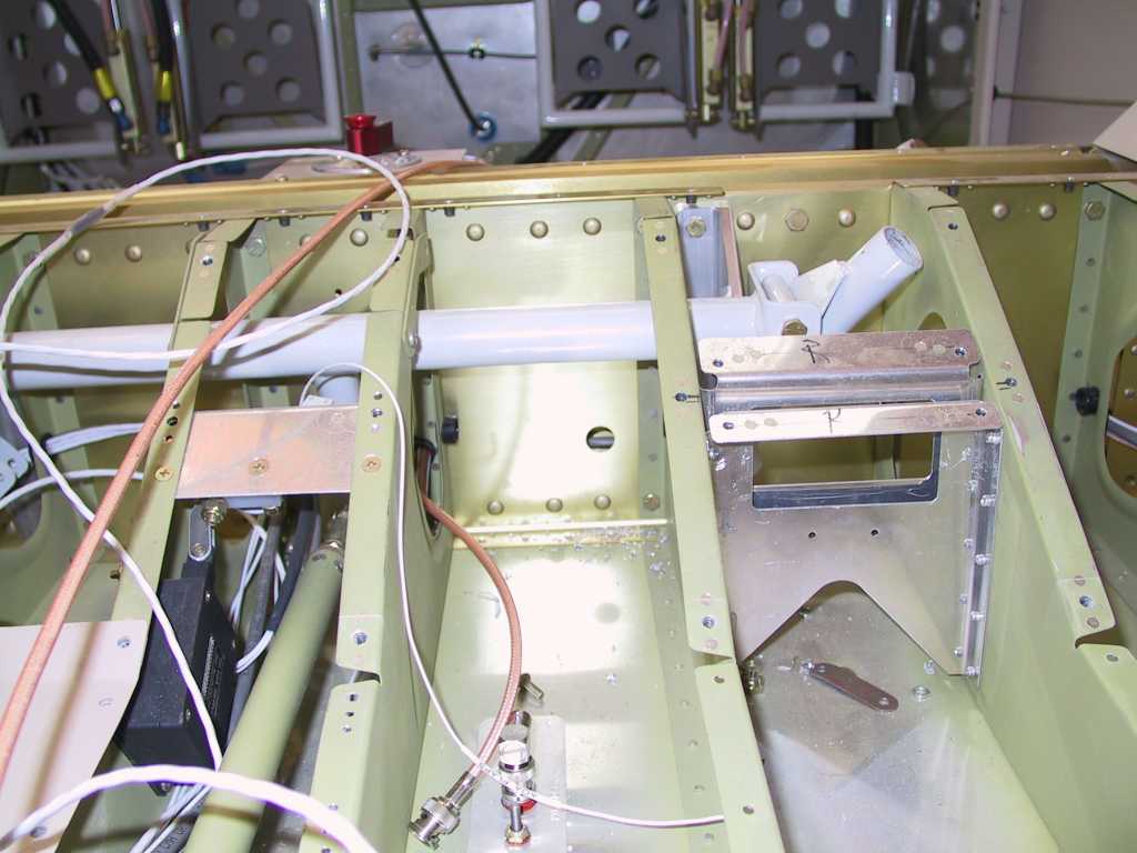
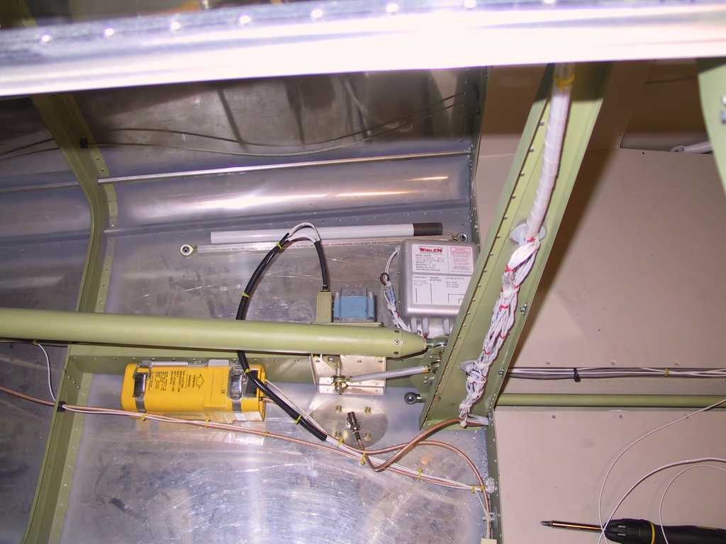
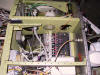
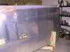
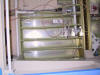
I wanted to get this rats nest of wires at least under
better control today. I'm running out of room in the snap bushings
going through the center section. One thing that I am very concerned
about is running the wires on the aft side of the center section. I
don't want anything to *ever* interfere with the stick. Can you
imagine? Well the mounts for the sticks don't provide a direct way
for wires to cross from left to right. It makes the wires stick aft,
right where the stick is. No bueno.
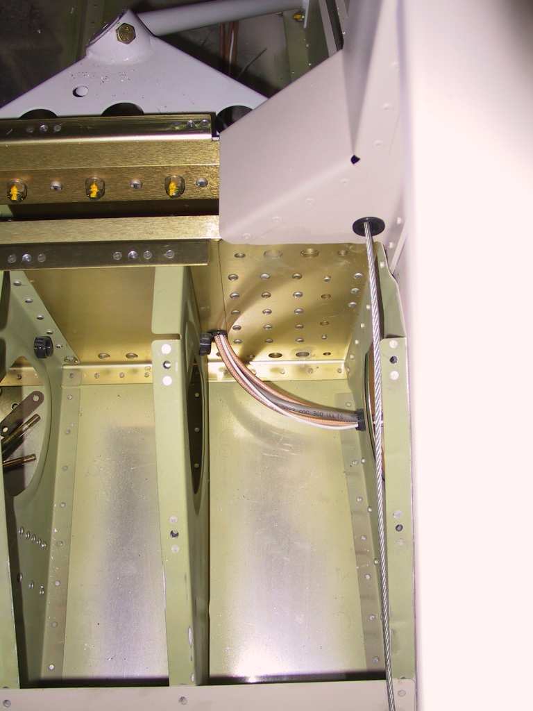
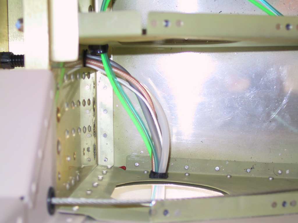
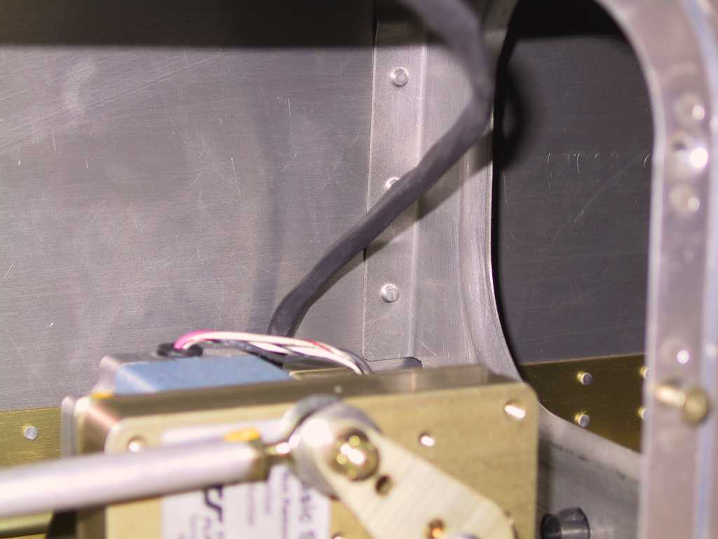
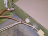
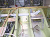
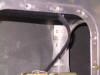
So after a lot of thinking I decided to run my antenna wires (RG400)
along the right side of the floor instead of down the middle and through
the center section. Also I'm making use of the room between the
forward and aft center section spars. I'll wrap these well later to
make sure there is no chaffing.
I only have a few more wires to run, namely all the wires for the AP
system, and I now have room to run them down the center of the floor.
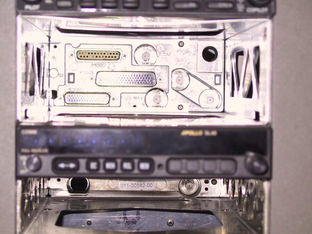
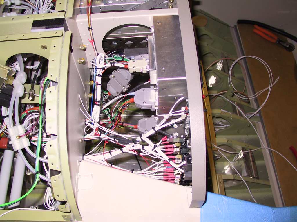
Just to make sure that John wired my stack as expected, and that I'm
sure of the wires I'm going to tap, I removed the GNS430 and GTX330 in
order to expose the connectors at the back. I used my trusty
voltmeter to make sure everything is what it should be. So far so
good.

Time to take apart the harness. What a mess. I can't do any
work yet on these wires because I don't have the High Density pins yet.
I ordered them from some obscure internet site. When I get the pins
I'll let you in on where I found them. Finding "machined" HD pins is
a pain. The crimp type with the little tabs suck hind tit. I
also bought these little labels for the antenna wires.
   |
| 10/29/04 |
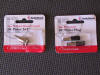
Received some goodies in the mail today. Not the
stuff I wanted but stuff anyhow. Two bags of those glue-on wire tie
holders.
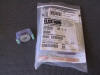
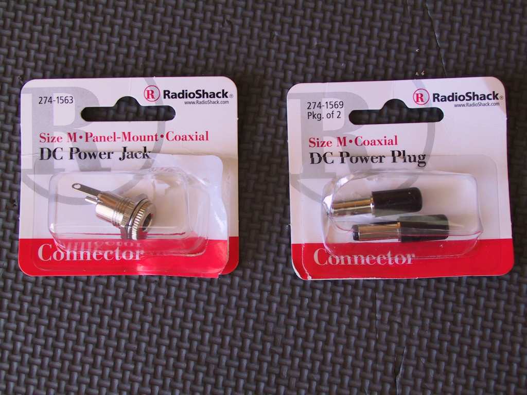
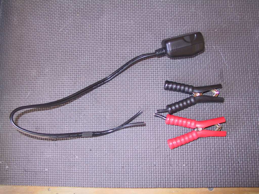
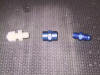
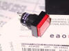
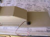
And I stopped by radio shack today because I don't want to install that
ugly 12 cigarette lighter adaptor on the panel. I purchased these
little 12V connectors. One I'll install on the end of a cigarette
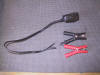
adaptor with a cable and the other on the panel. Now all you will
see is a little connector on the panel. The 12V accessories will
connect to the cable I'm making by cutting off the battery clamps on the
last picture.
  |
|
10/30/04 |
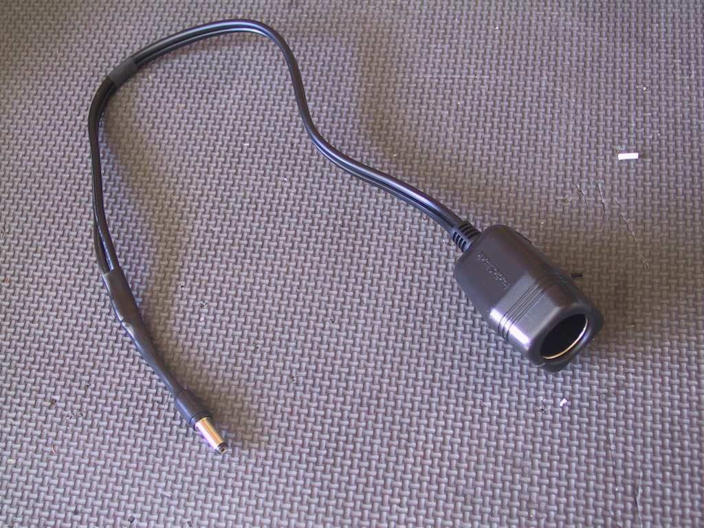
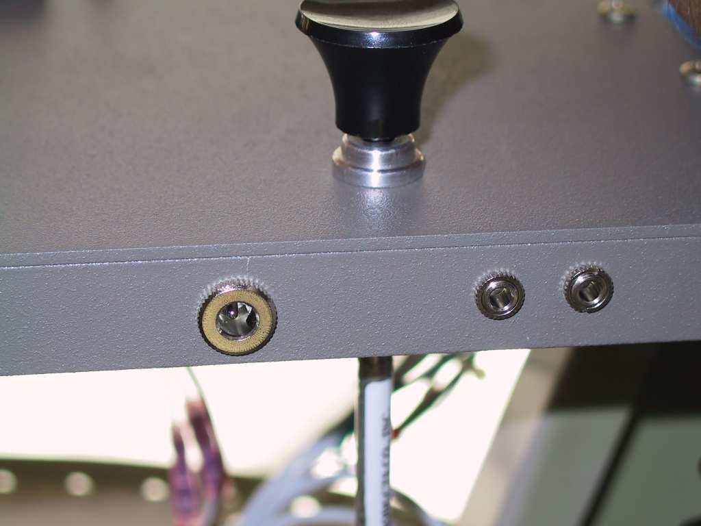
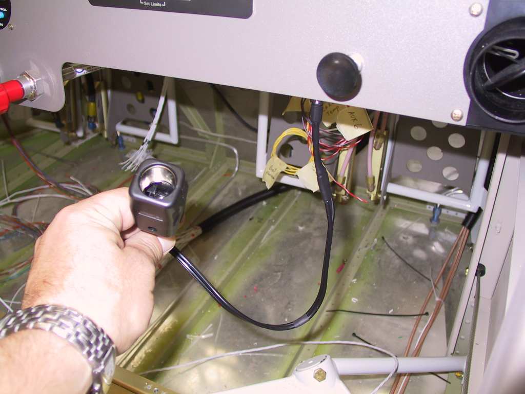
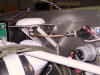
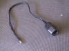
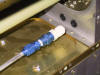
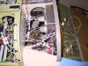
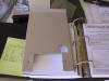
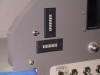
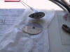
Continuation of where I left off yesterday. Here's
the power piggy-back I made. Plug the small end into the hidden 12V
connector located on the bottom of the pane and plug any 12V device into
the big end. In the second photo you can see the 12V adapter on the
left and music1 and music2 inputs on the right.
  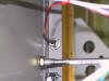 
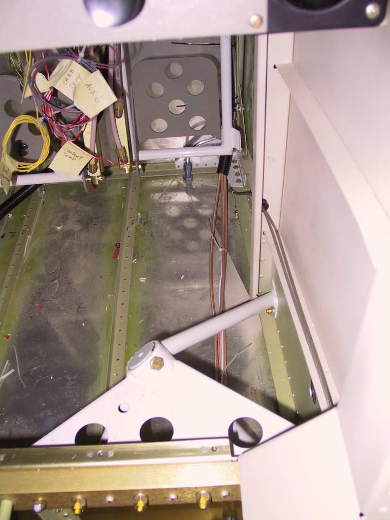
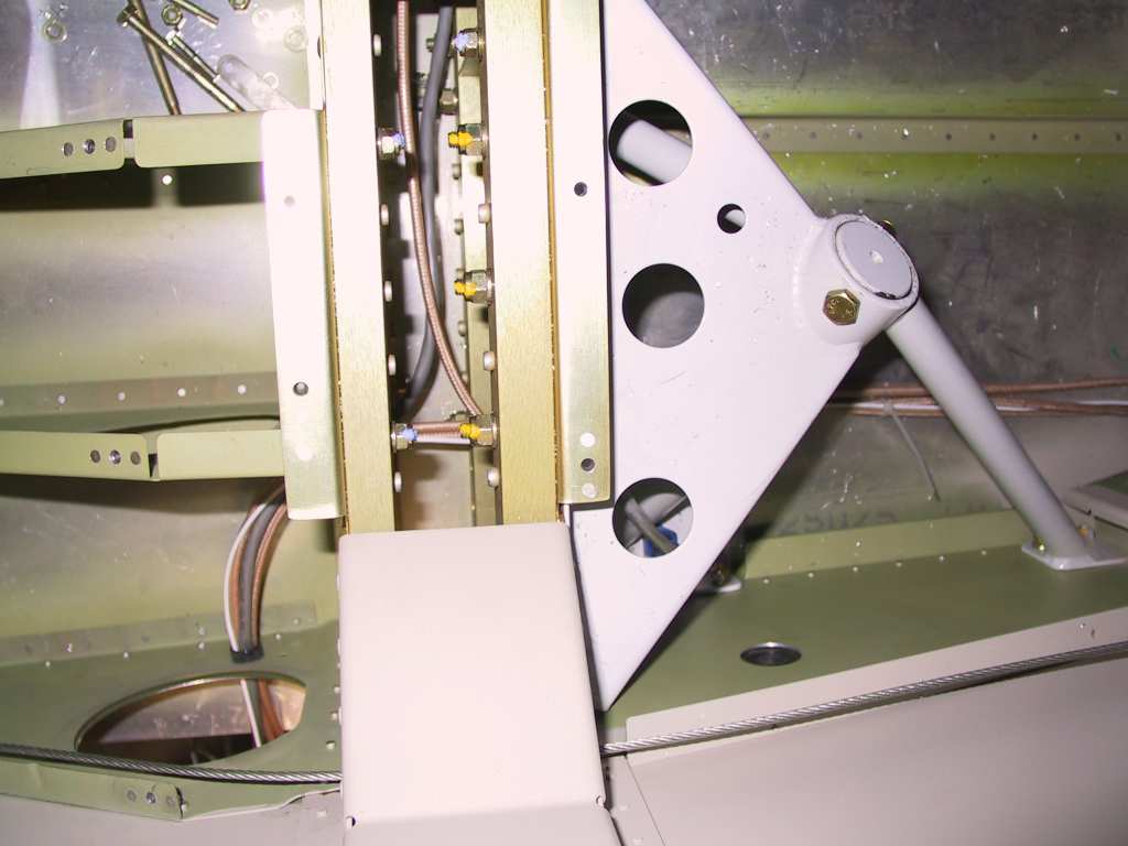
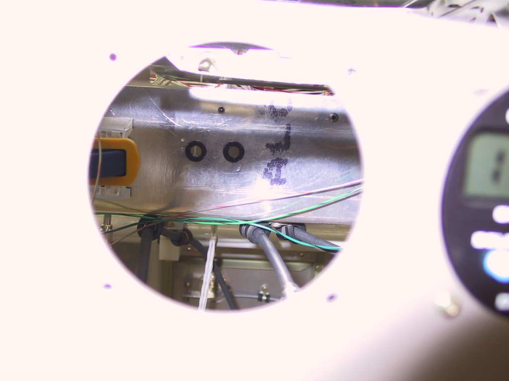
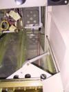
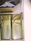
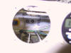
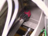
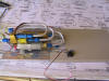
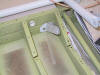
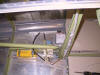
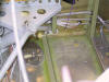
Looking through the AP panel hole you can see the two holes drilled and
filled with bushings for the Pitot and Static runs where they go through
the sub-panel. Pic 2 is the a/p connected to the tubes and pic 3 is
where they come up and mate to the AHRS.
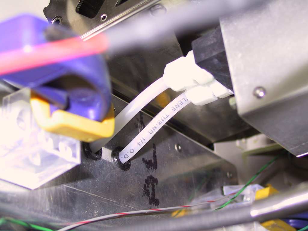
Looks like I'm gonna have to punch one additional hole through the
center section webs. I don't have enough room for the AOA tubing.
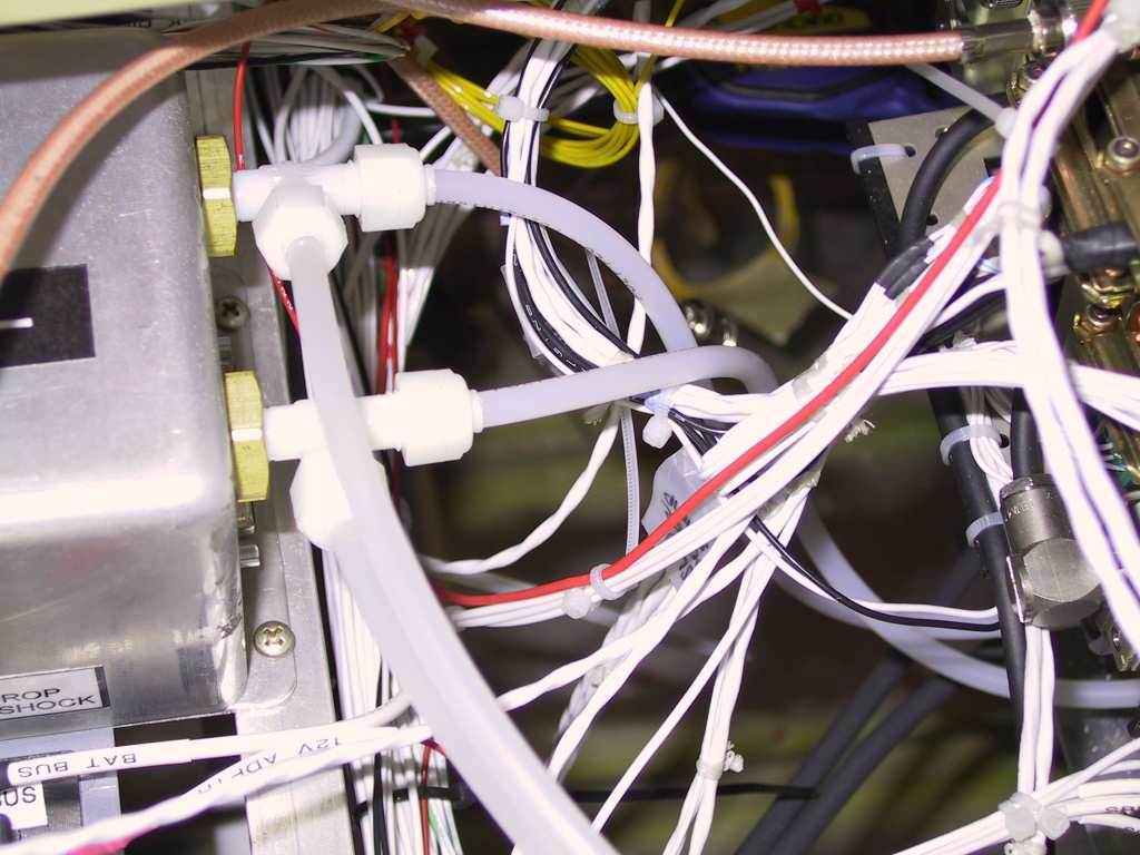
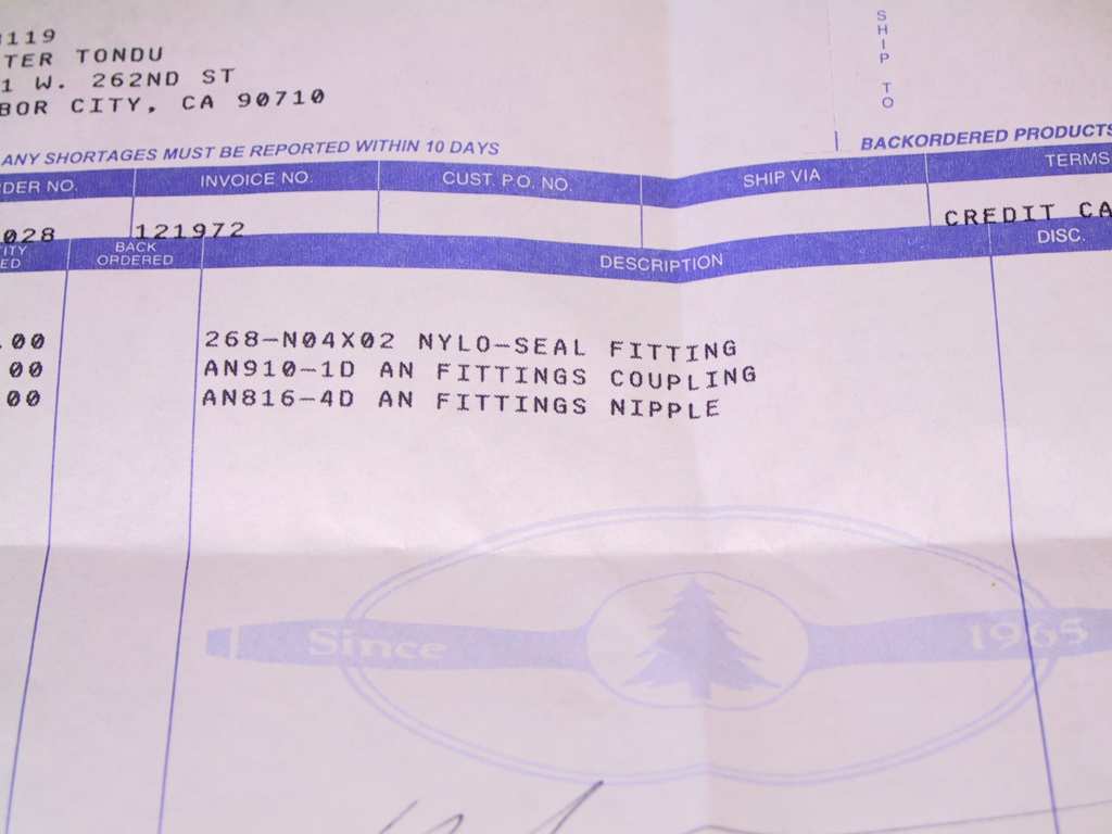
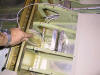
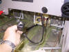
I've been considering making the aluminum pitot tube run transition to
flexible nylon tubing for some time now. So off to Spruce I went to
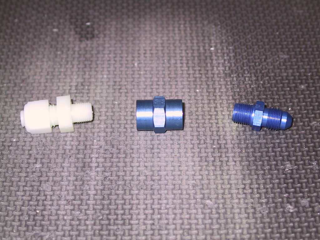
get some parts. Here's what you'll need to convert from aluminum
compression to plastic tube. I mad the changeover at the inspection
panel closest to the wing root. I have the tubing exiting the
fuselage now and I'll feed it in through the wing when I mate the two.
   |
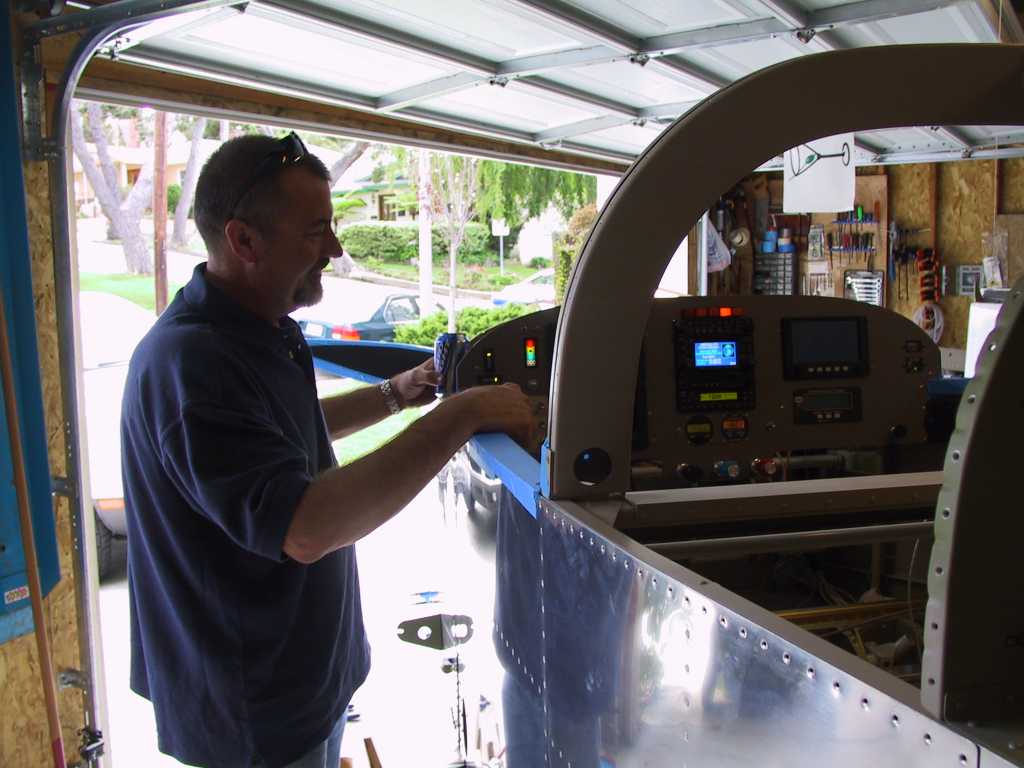
| 10/31/04 |
BOO! Happy Halloweeeeeen. I'm sitting at the
computer with all the lights off in the house. I don't have any
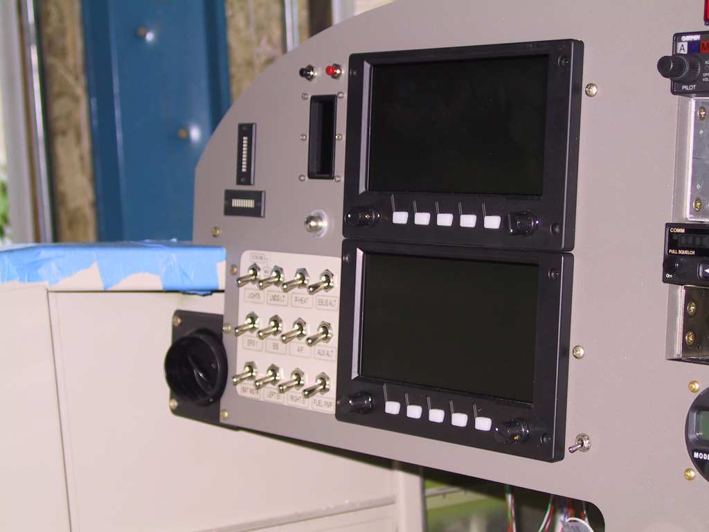
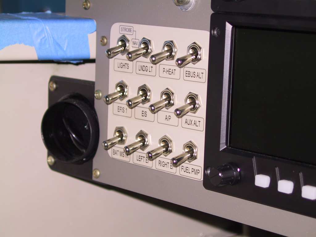
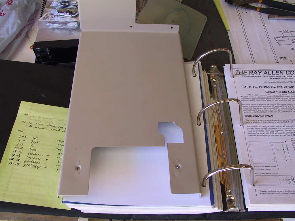
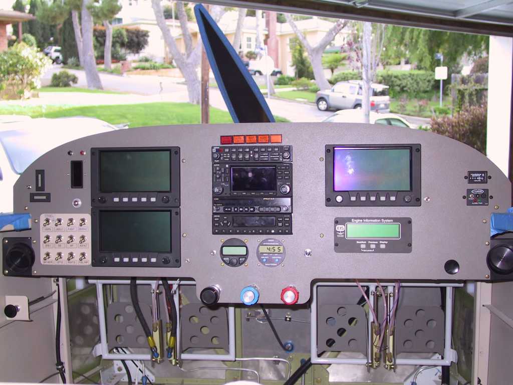
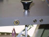
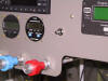
candy. :) I made a backing plate for the switches and painted it
the same color as the interior of the plane. The powder coated panel
doesn't like those little switch legend stickers since the texture is
rough. The little switch labels are made with a Brother P-touch
2600. Very nice little machine. Hook it up to your computer,
design your labels and print away.
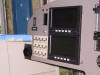 
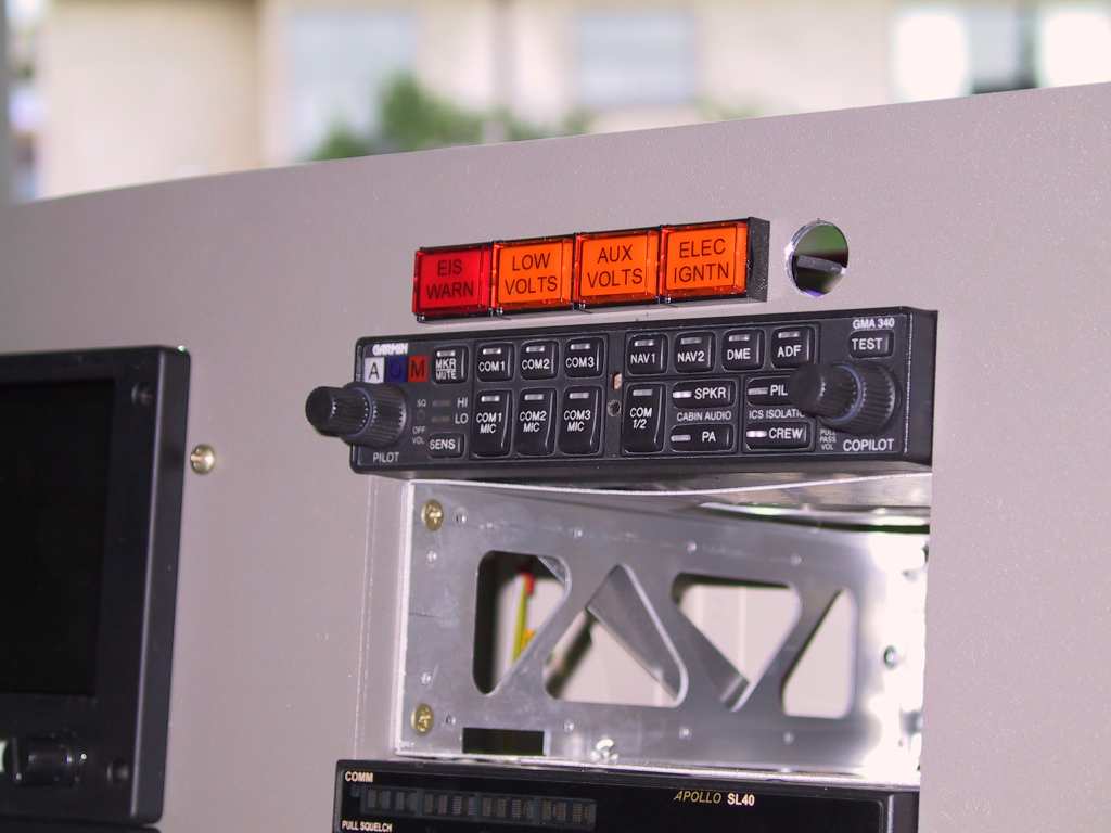
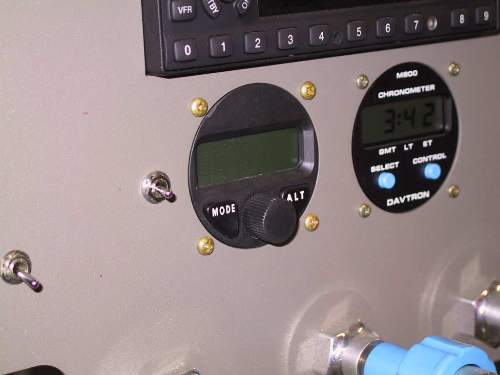
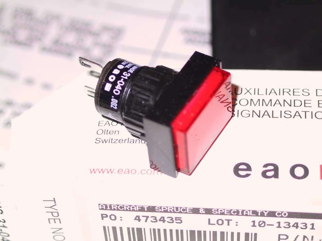
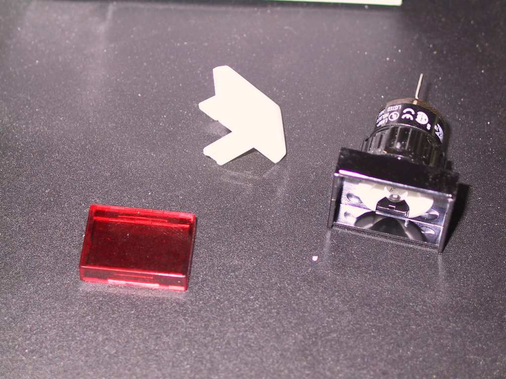
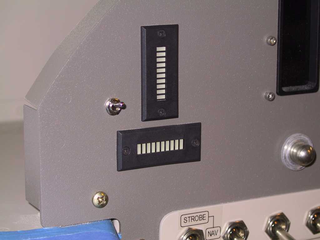
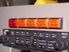
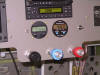
I added two more enunciator lights at the top of the panel. One
for the EIS4000 and the other will be for the EFIS units. Here
again, the enunciator labels are printed with the P-touch. You can
replace the lens caps of these little lights with different colored
lenses, they just snap off and on. There is a sub lens onto which
you place your little clear label stickers.
 |
|
11/14/04 |
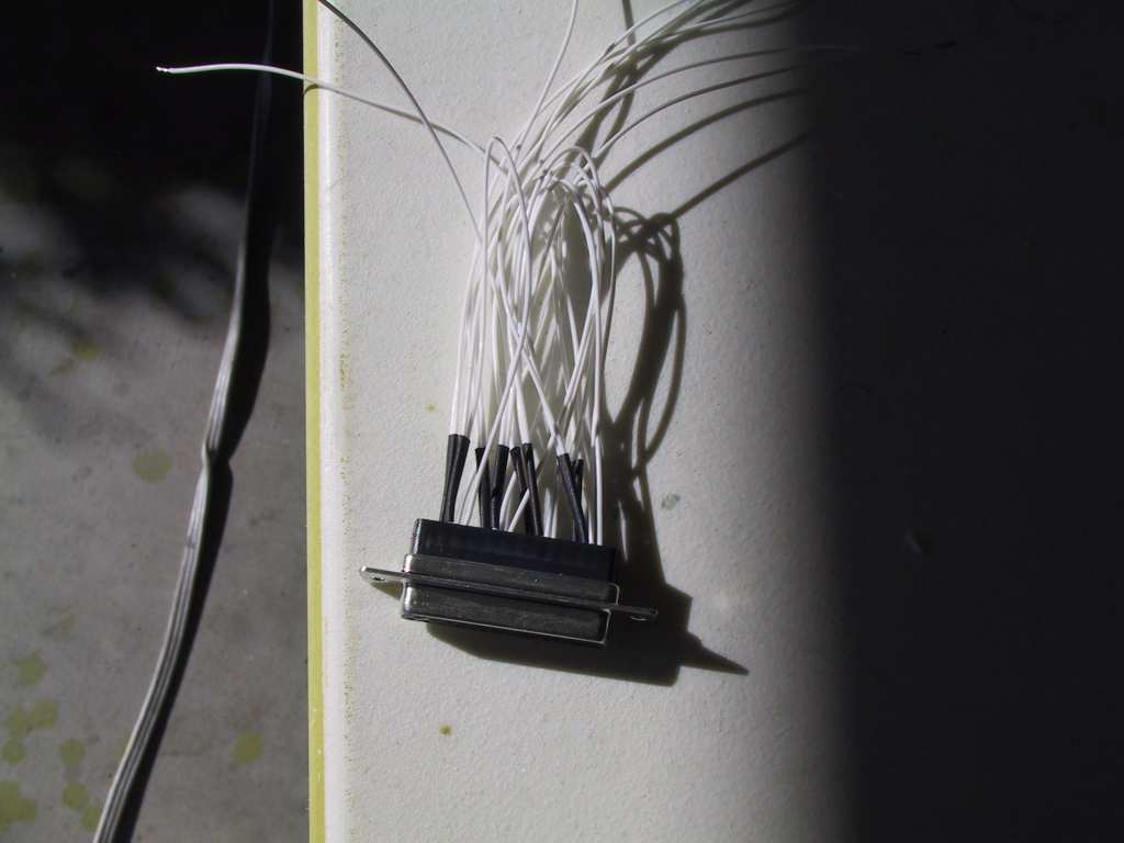
More wiring, and the end *is* in sight, finally. I
have purchased the GRT ARINC 429 adapter but you should run all the
localizer and glide slope wires to all displays as a backup. That's a
total of eight wires to three display, or 24 shared connections.
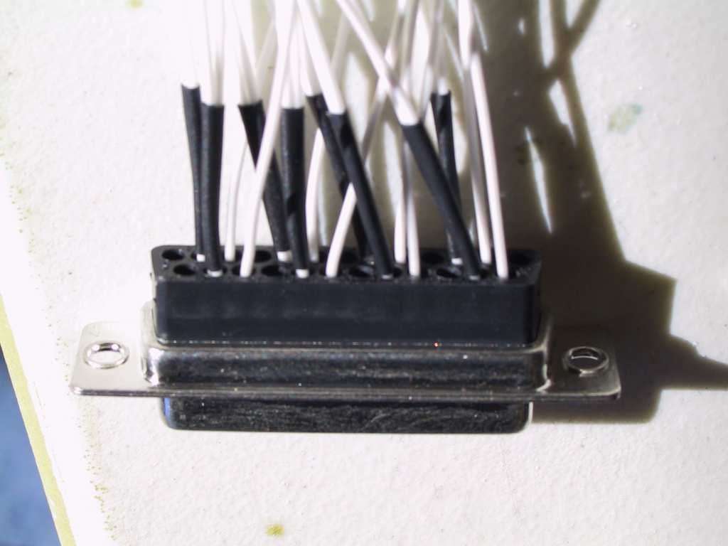
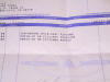
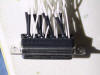
I've found that a 26Ga and 22Ga wire will both fit into a d-sub connector.
I place the 26Ga wires as jumpers between the pins. Be sure to heat
shrink the connections as those 26Ga wires a plenty fragile. Here's
24 of 25 pins connected in the dsub.
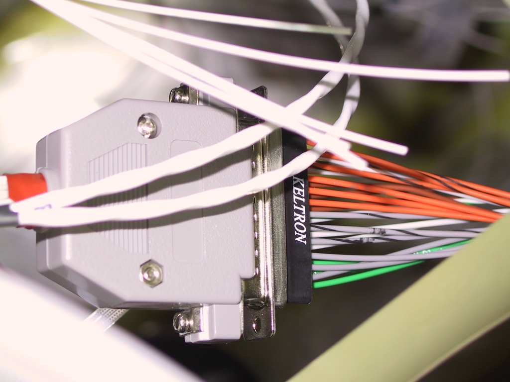
Then connected with the three display unit wires (plastic cover is off
one half)

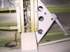
I used a Triple pole double single throw switch to switch between the
EFIS and GPS commanding the AP. Here it's installed.
I'm starting to really like these enunciator lights. They're
cheap, look ok and are very easy to label or re-label should you decide to
change things later on.
At the end of the day, I was eating spaghetti.
 |
|
11/15/04 through
11/25/04 |
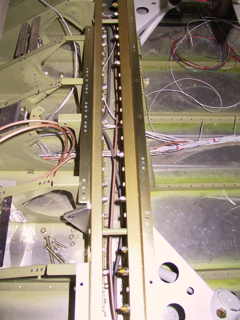
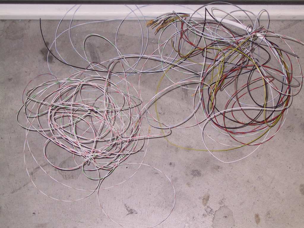
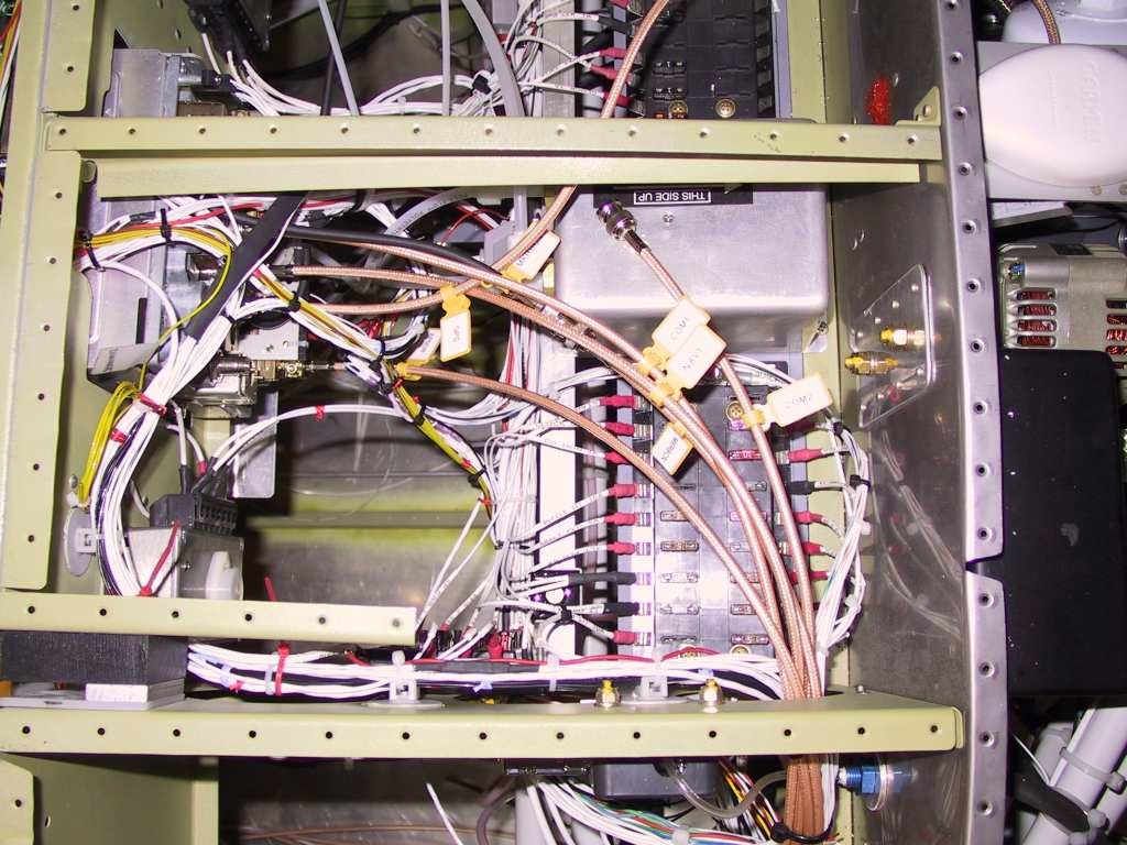
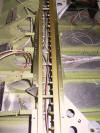
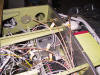
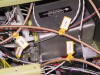
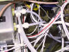
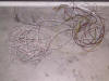
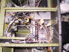
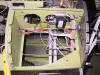
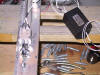
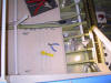
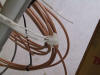
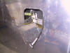
I have been working on the plane. Just wire by
stinking wire. This has got to be the most tedious business of
building. I've had to take a few days off here and there to clear my
head. I'm making steady progress but pictures here would be
worthless. Plus my camera is starting to act-up. I don't know
how much longer it will be with us. I may kill it to justify another
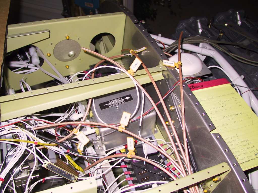
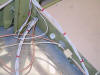
one. Anyway, here are some shots of the wiring cluster as it stands now.
I'll be replacing most of the wire-ties with cloth wraps eventually.
The only thing that needs to be wired now is the AP. There are a few
other items but they are no-brainers.
I have run into one significant snag in all of this wiring. Vans
callouts for wiring runs are simply not enough if you plan an IFR platform
with dual Nav/Coms and the works. The conduit holes running fore and
aft are too narrow. But a larger bushing than called out for all
fore and aft runs with the exception of the outermost holes on the center
section. You can't enlarge those because of clearance issues.
Remember, once you have run and fixed a good chunk of wires thought the
conduits you are pretty much committed unless you want to undo all of
them. You can't make a hole bigger with the wires in it!@! Go
Bigger Early! I now have to run the seconds com antenna at the
forward fuselage instead of the wingtip because I have no more room for
wires coming through the center section. It's ok though as a normal
antenna will work better. So what if I lose a knot or two...
Last week I helped David Richardson rivet the last two panels onto his
final wing. He's got both of them "done". So in retribution he
stopped by and we managed to get the bottom panel onto one of my wings.
Thanks David.
 |
| 11/27/04 |
I'm losing the will to succeed. If I can just get
past this wiring. I need a boost. I've even lost the will to
update the website. |
| 11/28/04 |
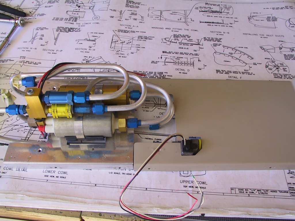
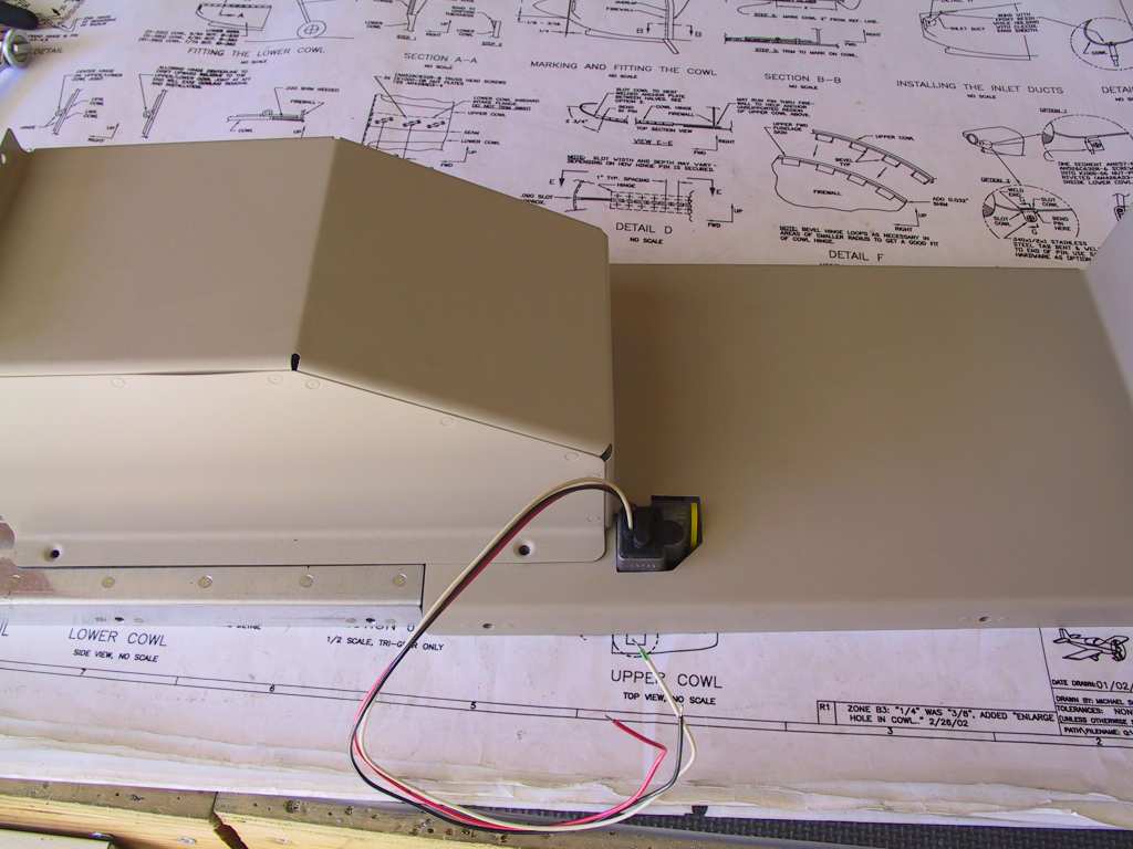
More wiring. Then more wiring. Now that I have
the wiring mess under control it was now time to start thinking about
where the flowscan fuel flow transducer is going to sit. It needs
about 5 inches of straight or almost straight pipe before and after the
transducer. The most likely place is just after the AFP fuel
pump/filter combo on the floor in the cabin. Since the transducer is
taller than the cover plate I cut a notch for it. This will all be
covered with carpeting and you'll never see it.
   |
|
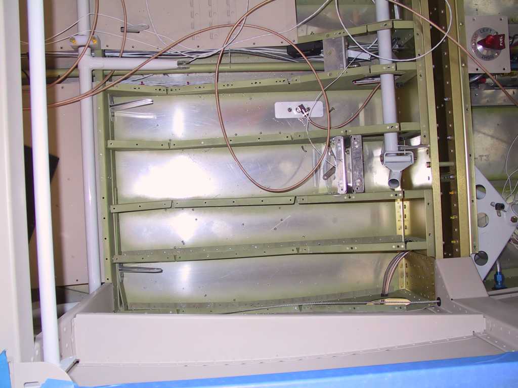
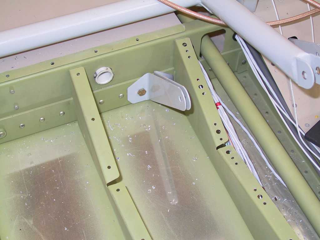
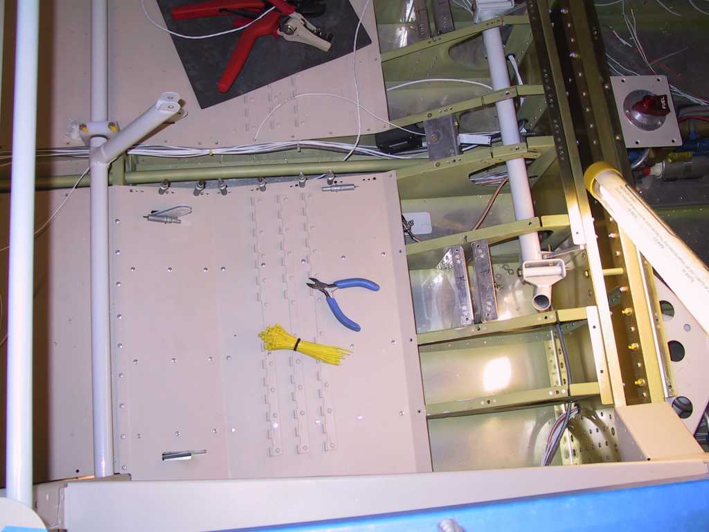
2/27/05 |
If you are building an IFR plane with all the
bells and whistles, including up to 6 antennas (com1, com2, nav, gps, mrkrbkn,
transponder), and autopilot, and strobes, you *WILL* need to make one or two
additional conduit runs fore to aft. Trust me. Before closing up the
baggage and passenger floor boards, PUT ONE OR TWO ADDITIONAL runs in place.
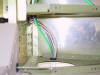
Here's how I did it. First I removed the passenger seat floorboard.
Trust me, do this *before* you put these in permanently. Then I drilled a
hole on each side of the baggage floor bulkheads to allow a thin walled pvc
conduit. I also drilled a hole through the center section spar web.
I called Van's a while back about doing this and was given the "blessing". The pvc
is held in place with some wire ties.
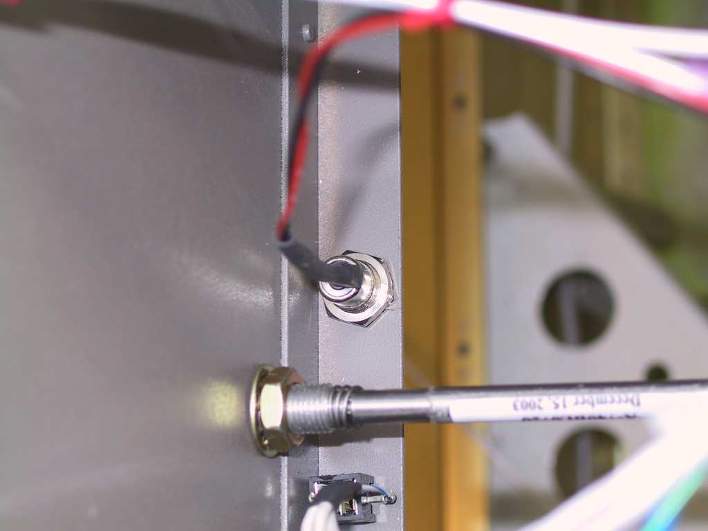
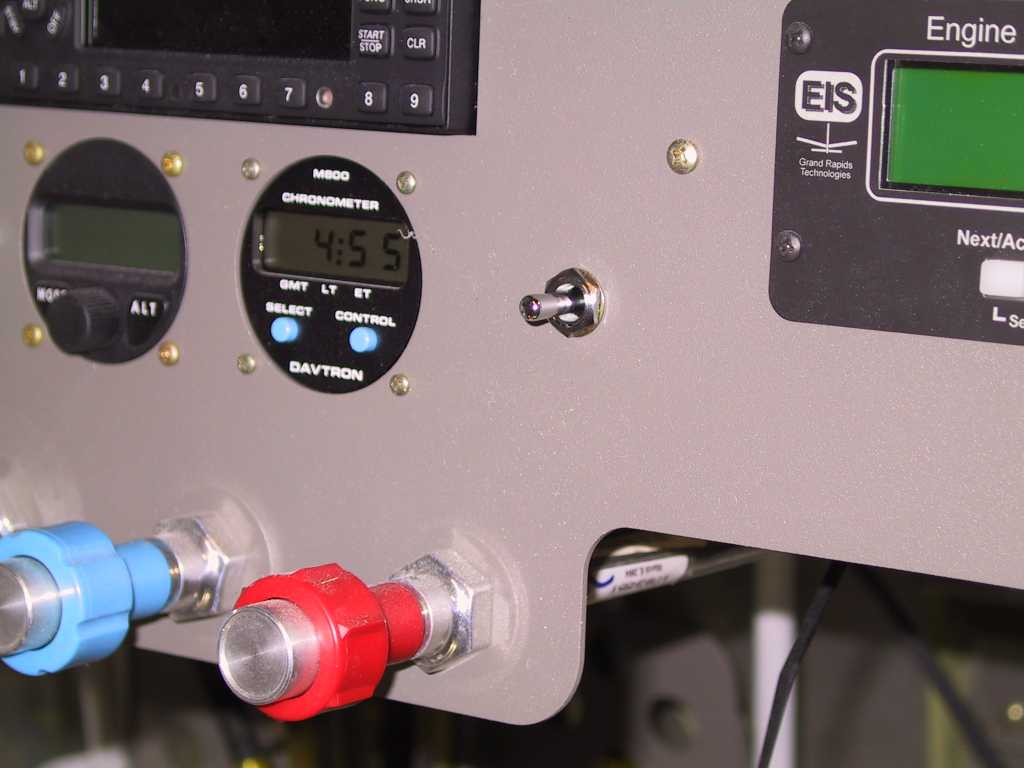
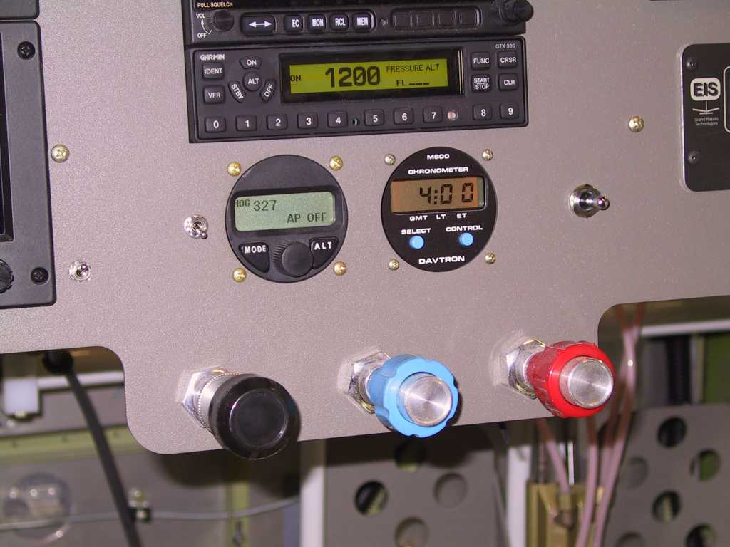
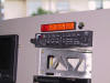
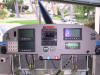
Next I installed the dimmer switch for the Ray-Allen led trim
indicators. This little switch just feeds a positive 14 volts to the
indicators to dim. I tapped off the starter pushbutton lead, no sense to
run a wire all the way back.
Next I installed the FPS flap position switch. This seemed
like a good location. And, it's the last switch, or anything for that
matter that will go on the panel, that I can think of.
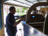
This is the state of the panel now. Beauticious.
 |
|
2/28/05 |
Today, my cousin Tim, whom I haven't seen in
literally years, stopped by for the night as he was in town. Really good
to see him after all these years. He and I did a lot when we were younger
together, back when I was still in High School. Anyway, since he was here
admiring all the work so far done, I decided to put him to work, slave driver
that I am. So why not tackle one of the last wiring jobs left, the
autopilot. Since I had removed the floorboards and added an additional
wire run (Don't forget, you WILL need to do this, trust me, I can't say it
strongly enough. Do it Before you permanently install the seat pans.)
Anyway, here's Tim (I know, terrible picture) with beer in hand,
working hard :) We had just completed the first test of the AP and it was
successful the first time.
And now a gratuitous shot of the last item on the panel to
receive power. I still have to check the wiring between it, the EFISsss
and the GNS430.
 |
| 3/2/05 |
FPS flap position sensor gets temporarily
mounted.
Seat pan gets reattached and autopilot wiring is nearing
completion.
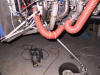
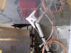
I also added a bit of silicone baffling material around the
scat tubes because it touches the cowl just a bit and I don't want any chafing.
 |
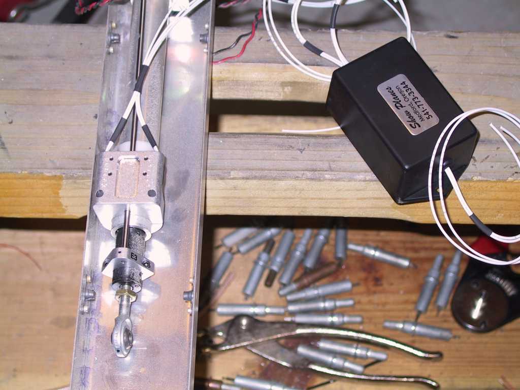
| 3/5/05 |
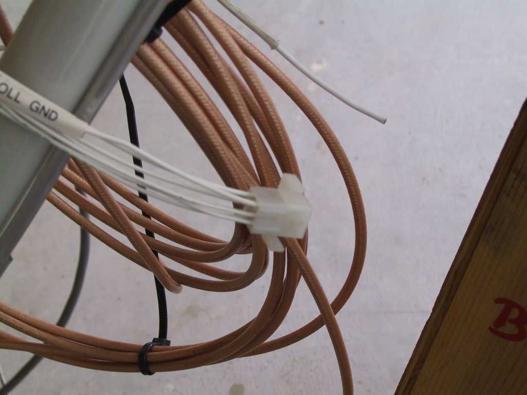
Time to finish the AP wiring. The wires
exit at the wing root and terminate in a 9 pin molex connector. I then
fabricated the 7 wire run into the wing conduit and had it exit the conduit at
the servo.
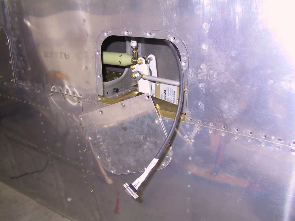
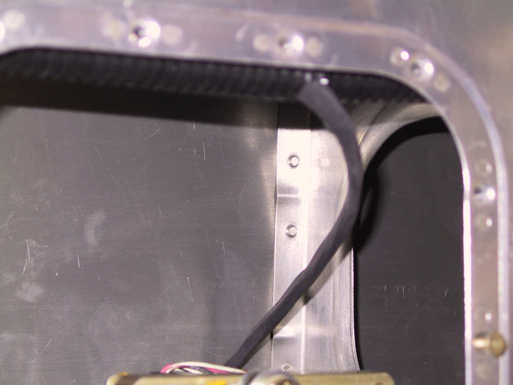
One thing that's not so pleasant is that the DB9 connector on
the servo faces opposite of the inspection port. So I had to remove the
servo in order to fasten the DB9 connector firmly. Done deal.
  |
|
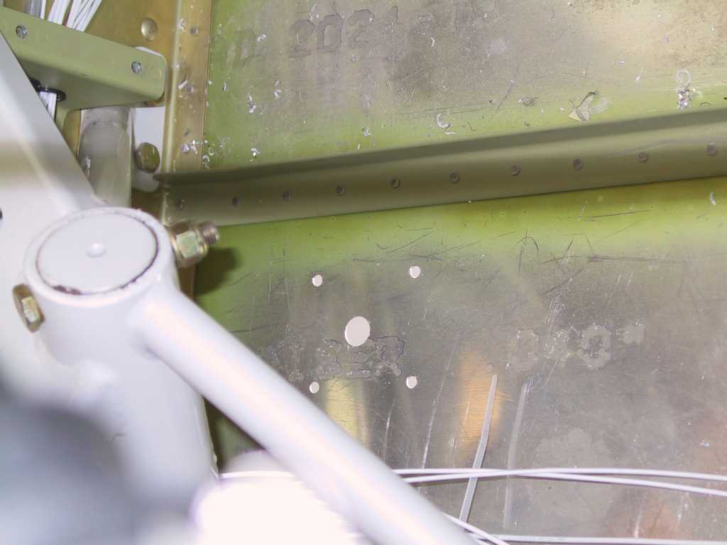
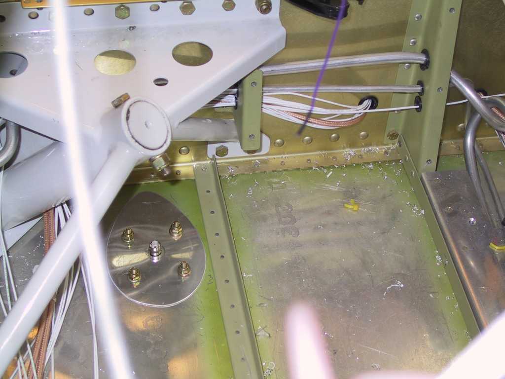
3/6/05 |
I've been stuck lately as to where to mount the
COM2 antenna. I had high hopes of getting it in the wing tip but alas
there just is no room to run this big fat cable. So I've decided to place
it just inboard of the gear weldment. It'll be next to impossible to get a
shoe on it here and I'll use a 90 degree fitting just to keep the antenna cable
out of the way. I made a backing plate for it, drilled it and mounted it.
    |